|
Step |
Action |
|---|---|
|
1 |
Verify whether the slide on the Bus Bar Module can be moved easily. If not, loosen the screws securing the slide to the Bus Bar Module. |
|
2 |
Connect devices via the slide of the Bus Bar Module. |
|
3 |
Tighten the screws of the Bus Bar Module (torque: 2.5 Nm / 22 lbf in). |
|
4 |
Mount the shock protector covers LEFT TOP (1) and RIGHT TOP (2) on the outside of the Bus Bar Module combination. For important safety information, follow the instructions in the first safety message after this table. Shock protector covers 
Shock protector covers on the outside of the Bus Bar Module combination 
|
|
5 |
Connect the additional protective ground conductor with the ring cable lug and the M5 screw to the heat sink of the power supply (tightening torque: 3.5 Nm (31 lbf in)). |
|
6 |
Follow the assembly based on the heat sink: oLock washer oRing cable lug oLock washer oWasher oScrew |
|
7 |
Connect the plug-in connector CN5 ”24 V supply” to the power supply. For important safety information, follow the instructions in the second safety message after this table. |
|
8 |
Connect the plug-in connector CN6 "AC supply" to the power supply. |
|
9 |
Connect the Sercos cable CN2 (CN3) to the power supply |
|
10 |
Insert the other end of the Sercos cable CN2 (CN3) into the drive module. NOTE: Depending on the device combination, choose the appropriate Sercos cable length. NOTE: If possible, establish a Sercos connection via the ring topology (2). NOTE: If Sercos devices are assigned via the topological addresses (IdentificationMode = TopologyAddress) to the PacDrive LMC, then consider the following: oConnect your Sercos device to the PacDrive LMC either completely via Sercos port 1 (PacDrive LMC Eco: CN5, PacDrive LMC Pro/Pro2: CN12) in line topology or in ring topology using Sercos port 1 and 2 (PacDrive LMC Eco: CN5/CN6, PacDrive LMC Pro/Pro2: CN12/CN13). oDo not connect the Sercos devices to the PacDrive LMC via double line topology (PacDrive LMC Eco: CN5/CN6, PacDrive LMC Pro/Pro2: CN12/CN13). oDo not connect the Sercos devices to the PacDrive LMC only via Sercos port 2 (PacDrive LMC Eco: CN6, PacDrive LMC Pro/Pro2: CN13). Line topology and ring topology 
1 Line topology 2 Ring topology |
|
11 |
Connect the plug-in connector CN4 "Ready relay output" to the power supply. |
|
12 |
Connect the plug-in connector CN6 / CN11 "Inverter Enable" to the drive module (Lexium 62 Cabinet Drive). |
|
13 |
Optionally, connect the plug-in connector CN4 "IO" to the drive module. |
|
14 |
Optionally, connect the plug-in connector CN5 "IO voltage supply" to the drive module. |
|
15 |
Connect the "Motor connector Axis A" CN8 to the drive module. |
|
16 |
oConnect the "Motor connector Axis B" CN10 to the double drive, if available. oConnect the "Machine Encoder Output" CN12 to the advanced double drive, if available. |
|
17 |
Connect the "Encoder plug-in Axis A" CN7 to the drive module. |
|
18 |
Connect the "Encoder plug-in Axis B or Machine Encoder" CN9 to the double drive, if available. |
|
19 |
Connect the "Encoder output plug" CN12 to the advanced drive, if available. |
|
|
|
ELECTRIC SHOCK CAUSED BY HIGH LEAKAGE (TOUCH) VOLTAGE |
|
oAttach the shock protector covers on the extremities of the Bus Bar Module combination. oApply power to the device only if the shock protector covers have been attached to the extremities of the Bus Bar Module combination. |
|
Failure to follow these instructions will result in death or serious injury. |
|
|
|
INSUFFICIENT GROUNDING |
|
oUse a protective ground conductor with at least 10 mm2 (AWG 6) or two protective ground conductors with the same or larger cross section of the conductors supplying the power terminals. oVerify compliance with all local and national electrical code requirements as well as all other applicable regulations with respect to grounding of all equipment. |
|
Failure to follow these instructions will result in death or serious injury. |
How to Assemble the Lexium 62 DC Link Terminal
|
Step |
Action |
|---|---|
|
1 |
Mount the strain relief (1) to the control cabinet wall using two M5 screws. 
|
|
2 |
Remove insulation of wires and apply cable end (without insulating sleeve) to flexible wires. |
|
3 |
Insert the protective earth ground wire into the green/yellow terminal (2) and tighten the clamping screw (3) (torque: 4.5 Nm / 39.8 lbf in). 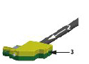
|
|
4 |
Insert the other 4 wires (DC- and DC+ wires to the black terminals, 24 V, and 0 V wires to the blue terminals) and tighten the clamping screws (torque: 4.5 Nm / 39.8 lbf in). NOTE: The terminals are not connected to the Bus Bar Module yet. For important safety information, follow the instructions in the safety messages after this table. |
|
5 |
Plug in the terminals with the wires to the Bus Bar Module connectors in the correct order (top to bottom). (4). 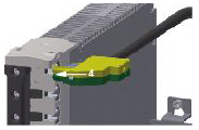
|
|
6 |
Clip on the retaining bracket (5) to the Bus Bar Module. 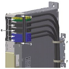
NOTE: The retaining bracket is not securely seated until you hear an audible click. Result: The terminals are secured against twisting. |
|
7 |
Tighten the screws of the terminals (6 in the graphic presented in step 6) on the Bus Bar Module (torque: 2.5 Nm / 22 lbf in). |
|
8 |
Secure the five wires on the strain relief by using cable ties (7 in the graphic presented in step 6). NOTE: If using single-core wires within one cabinet, you must conform to the following wiring rules: oThe solid-core DC- and DC+ wires must be installed side-by-side and must be attached to each other (for example, by cable ties). oThe solid-core 24 V and 0 V wires must be installed side-by-side. |
|
9 |
Optionally: If you couple two control cabinets, ground the cable shield by using the strain relief in combination with a shield connection terminal block (8) (Icotec SKS 20-35 or Phoenix Contact SK35). NOTE: A shield connection terminal block can be used for cables with diameters between 20 mm (0.79 in) and 35 mm (1.37 in). 
|
|
|
|
FIRE, ELECTRIC SHOCK, OR ARC FLASH WHEN USING LEXIUM 62 DC LINK TERMINAL |
|
oThoroughly verify the proper isolation of DC-/DC+ to PE (Protective Earth/ground) with an appropriate measuring instrument before first power on. oVerify that the terminals are fully inserted on the Bus Bar Module. oDo not connect DC+ to PE, 24 Vdc, 0 V or to DC-. oDo not connect DC- to PE, 24 Vdc, 0 V or to DC+. oInstall the bus terminal connectors in the correct order 1 to 5 as follows: oPE (1, green/yellow) oDC- (2, black) oDC+ (3, black) o+24 V (4, blue) o0 V (5, blue) oAlways install the full complement of the five connectors and the retaining bracket of the Lexium 62 DC Link Terminal. oAlways wire at least the PE, DC- and DC+ terminals out of the 5 installed connectors. oVerify that the PE (Protective Earth/ground) terminal (1, green/yellow) is always connected to protective ground (earth) using a conductor of at least 10 mm2 (AWG 6). oVerify compliance with all local and national electrical code requirements as well as all other applicable regulations with respect to grounding of all equipment. oDo not insert more than one wire per terminal. oTighten clamping screws of the terminals in conformance with the torque specifications. oOnly use the cable conductors with the appropriate cross-sections and current carrying capacities. oOnly use wires of appropriate cross-section as indicated. |
|
Failure to follow these instructions will result in death or serious injury. |
|
|
|
ELECTRIC SHOCK |
|
oOnly use stranded wires with appropriate cable ends or rigid wire. oUse only cable ends without an insulating sleeve. oThoroughly verify that the cable ends are fitted correctly such that the wire is secure and no wire strands are exposed. oMark the wires to prevent incorrect connections. |
|
Failure to follow these instructions will result in death or serious injury. |
|
|
|
ELECTRIC SHOCK |
|
oMount the retaining bracket as instructed in the product documentation. oEnsure that the retaining bracket is fixed securely to the bus bar module. oDo not remove the retaining bracket or the terminals while the product is energized. |
|
Failure to follow these instructions will result in death or serious injury. |
|
|
|
ELECTRIC SHOCK |
|
oEnsure that the cable ties are securely holding the wires/cables on the strain relief component. oEnsure that all forces acting on the terminals and connected wires/cables are minimized. |
|
Failure to follow these instructions will result in death or serious injury. |
|
|
|
IMPROPER WIRING BETWEEN CONTROL CABINETS CAUSES ELECTRIC SHOCK |
|
oOnly use appropriate and certified cables according to the applicable standards. oOnly use the cables with the appropriate cross-sections. oOnly use cables outside the control cabinet. oObserve the bending radius of the cable/wire specification of the manufacturer. oThoroughly verify the cables/wires for defects and/or damages after the installation. oUse cable ducts and other appropriate measures outside of the control cabinet protecting the cables/wires from damage and mechanical stress. oRemove insulation accurately according to the stripping length of the cable conductor. |
|
Failure to follow these instructions will result in death or serious injury. |
|
|
|
FIRE HAZARD |
|
oDo not exceed an overall cable length of 3 m (9.84 ft) between any row without Lexium 62 DC Link Support Module or Lexium 62 Power Supply module and the next row with a Lexium 62 Power Supply module or Lexium 62 DC Link Support Module. oInstall a Lexium 62 DC Link Support Module for each drive of type LXM62DC13 in rows without Lexium 62 Power Supply module. oInstall all Lexium 62 Power Supply modules with linked DC Bus in the same control cabinet sharing the same mains contactor. |
|
Failure to follow these instructions will result in death or serious injury. |
|
|
|
HIGH ELECTROMAGNETIC RADIATION |
|
oDo not exceed a cable length of 15 m (49.2 ft) for single connections using Lexium 62 DC Link Terminal. oDo not exceed an overall cable length of 50 meters (164 ft) between one Lexium 62 device and any other Lexium 62 device connected via a Lexium 62 DC Link Terminal. |
|
Failure to follow these instructions can result in death, serious injury, or equipment damage. |
Device Combination and Sercos Cable Length
The table shows the Sercos cable length to wire of the Sercos communication for each device combination:
|
Connection |
Device left side |
Device right side |
Sercos cable length |
|---|---|---|---|
|
CN2 / CN3 |
LXM62PD20 / LXM62PD84 |
LXM62PD20 / LXM62PD84 |
130 mm (5.11 in) |
|
CN2 / CN3 |
LXM62PD20 / LXM62PD84 |
LXM62DD / LXM62DU |
130 mm (5.11 in) |
|
CN2 / CN3 |
LXM62PD20 / LXM62PD84 |
LXM62DC13C / LXM62DC13E |
150 mm (5.90 in) |
|
CN2 / CN3 |
LXM62DC13C / LXM62DC13E |
LXM62DC13C / LXM62DC13E |
130 mm (5.11 in) |
|
CN2 / CN3 |
LXM62DC13C / LXM62DC13E |
LXM62PD20 / LXM62PD84 |
115 mm (4.52 in) |
|
CN2 / CN3 |
LXM62DC13C / LXM62DC13E |
LXM62DD / LXM62DU |
115 mm (4.52 in) |
|
CN2 / CN3 |
LXM62DD / LXM62DU |
LXM62DD / LXM62DU |
90 mm (3.54 in) |
|
CN2 / CN3 |
LXM62DD / LXM62DU |
LXM62PD20 / LXM62PD84 |
90 mm (3.54 in) |
|
CN2 / CN3 |
LXM62DD / LXM62DU |
LXM62DC13C / LXM62DC13E |
115 mm (4.52 in) |