Mounting the Payload to the Rotational Modules
Here you will find the following information:
oMounting the gripper to the Rotational Modules
oFlange dimensions for the Rotational Modules
oSupply of the gripper on the Rotational Modules
Mounting the Gripper to the Rotational Modules
|
Step |
Action |
|---|---|
|
1 |
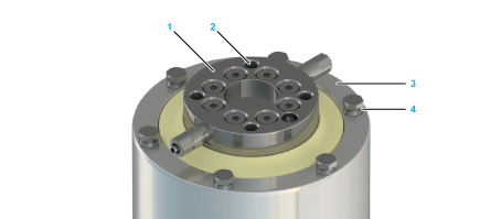
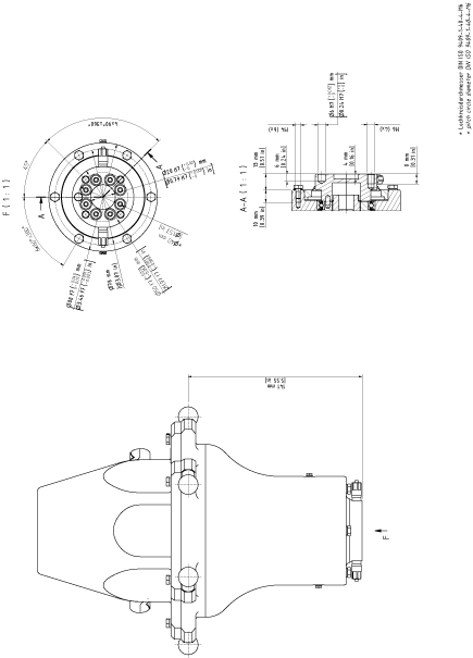
Fasten the gripper to the mounting points at the rotating flange (1) or on the fixed flange (3): oPitch circle diameter DIN ISO 9409-1, 40 mm (1.57 in): 4 x M6 (2), tightening torque: 4.2 Nm (37 lbf-in), strength class of the screw: at least A2-70 oPitch circle diameter 78 mm (3.07 in): 6 x M4 (4), tightening torque: 2 Nm (17.7 lbf-in), strength class of the screw: at least A2-70 For further information, refer to Flange Dimensions for the Rotational Modules. 
|
|
2 |
Calibrate the Rotational Module if this has not been done before mounting the gripper. For further information, refer to Calibrating the Double Rotational Module and the Rotational Tilting Module. NOTE: oObserve the permissible weights and distances that result in maximum tilting torque. oThe maximum torque must not be exceeded. For the respective values, refer to Mechanical and Electrical Data of the Rotational Modules. |
Flange Dimensions for the Rotational Modules

Supply of the Gripper on the Rotational Modules
|
Step |
Action |
|---|---|
|
1 |
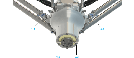
Connect the media line to one of the pneumatic plug-in connections (1.1 or 2.1) of the Rotational Module. The plug-in connection has a diameter of 4 mm (0.0157 in). 
For further information, refer to Supply of the Gripper. |
|
2 |
Connect the media line of the gripper to one of the associated connections (1.2 or 2.2) on the rotational flange of the Rotational Module. Straight fitting diameter: 4 mm (0.157 in) NOTE: oConnection 1.1 is linked to connection 1.2 oConnection 2.1 is linked to connection 2.2 |