Perform the following steps to verify the installation:
oVerifying the motor direction of rotation
oVerifying the coordinate system of the robot
|
Step |
Action |
|---|---|
|
1 |
Open the brakes. |
|
2 |
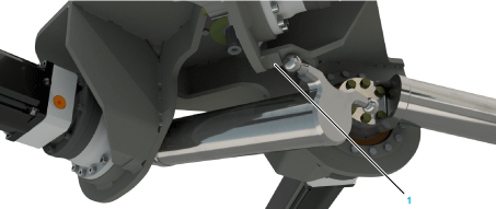
Carefully rotate an upper arm inwards until one ball pin contacts the limit stop on the underside of the housing (1). The following figure shows the upper arm of robot VRKP1/VRKP2 at the calibration position: 
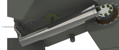
The following figure shows the upper arm of the robot VRKP0/VRKP4/VRKP5/VRKP6 at the calibration position: 
For further information, refer to Calibration of the Robot Mechanics. |
|
3 |
Verify that the angle indicated corresponds to the following value: oFor VRKP0: -187.3° (+/-0.1°) oFor VRKP1: -166.7° (+/-0.1°) oFor VRKP2•••WD: -164.0° (+/-0.1°) oFor VRKP2•••NC: -164.9° (+/-0.1°) oFor VRKP4: -184.5° (+/-0.1°) oFor VRKP5: -183.2° (+/-0.1°) oFor VRKP6: -183.6° (+/-0.1°) |
|
4 |
Move the arm outwards again until it is in a horizontal position (motor position ~0°). |
|
5 |
Repeat the process for all upper arms. |
Verifying the Motor Direction of Rotation
|
Step |
Action |
|---|---|
|
1 |
Slowly move the upper arms in manual mode, upwards and downwards. NOTE: Upwards (mathematically) is a positive change of an angle and downwards (mathematically) is a negative change of an angle. |
|
2 |
Verify that the direction of rotation is correct. |
|
3 |
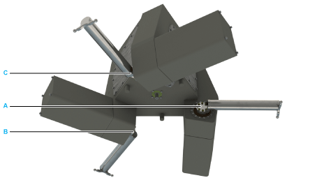
Verify that the parameterized motor moves and the motors A, B, C are arranged in a counterclockwise position. 
|
For further information, refer to Allocation of the Sercos Addresses.
Verifying the Coordinate System of the Robot
|
Step |
Action |
|---|---|
|
1 |
Slowly move the robot in manual mode in the direction of an axis of the coordinate system. |
|
2 |
Verify that the robot moves in a straight line in the direction of the axis. |
|
3 |
Verify that the robot moves in a straight line in a positive or negative direction of the coordinate system. NOTE: Arm of axis A is the cartesian coordinate X if coordinate system is not rotated by transformations variable i_lrRotationAngle. |
|
4 |
Repeat the process for all axes of the coordinate system. |
In case the robot does not move in a straight line on the path, proceed as follows:
|
Step |
Action |
|---|---|
|
1 |
Select the robot type when using the SchneiderElectricRobotics library. |
|
2 |
When not using the SchneiderElectricRobotics library, verify the correct parameterization of the transformation and the axes. |
|
3 |
|
|
4 |
|
|
5 |
In case the robot moves along a straight line but not in the direction of the required coordinate system, proceed as follows:
|
Step |
Action |
|---|---|
|
1 |
Verify the definition of the coordinate system on the transformation. |
|
2 |
Verify the definition of the motors in the correct sequence. |