Here you will find the following information regarding the Tool Connector:
oDescription of the tool flange and the assembly set
oLinking the Tool Connector to the tool flange
oAssembly set for the user installation
oFitting the Input/Output boards
oDescription of the solenoid valves
oDescription of the tool interface and the user input connections
Description of the Tool Flange and the Assembly Set
The Lexium S robots are fitted with a tool flange that can be used to hold the Tool Connector.
*1 Spot facing for DIN912-M6 screw
The Tool Connector is supplied with an assembly set containing the following elements:
o4x screw CHc M6x16
o4x safety washer
o1x square bracket
o2x screw CHc M3x12
o2x washer DIN 125-A3,2

Linking the Tool Connector to the Tool Flange
|
Step |
Action |
|---|---|
|
1 |
Fasten the bracket to the main body of the Tool Connector (two screws M3x12 and two washers). |
|
2 |
Fasten the main body of the Tool Connector to the tool flange (four screws M6x16 and four safety washers). |
|
3 |
Tighten the screws in diagonal sequence. Tightening torque: 7.3 Nm (65 Nm)) |
|
NOTICE |
|
LOSS OF IP54 DEGREE OF PROTECTION |
|
Add a sealing product on the tool flange before mounting it in place in order to comply with and maintain IP54 requirements. |
|
Failure to follow these instructions can result in equipment damage. |
NOTE: The label on the main body of the Tool Connector must be opposite the robot.
Assembly Set for the User Installation
Parts in the assembly set supplied:
o1x screw CHc M4x6
o1x washer DIN 125-A4,3
o1x lock washer DIN 6798-A4,3
o1x plastic clamp
o2x angle fittings for Ø 4/6 air hose
|
NOTICE |
|
INCORRECT INSTALLATION |
|
Ensure that, when the robot is in its straight position, the rotation axis (axis 4) is positioned on 0° and that the cables and hoses running through the ball screw are not twisted. |
|
Failure to follow these instructions can result in equipment damage. |
|
Step |
Action |
|---|---|
|
1 |
Cut off two pieces of air hose (lengths 10 mm (0.39 in) and 18 mm (0.71 in). |
|
2 |
Connect the pieces of hose to the fluted fittings and the angle fittings supplied. 
|
|
3 |
Push the installation cable and the two air hoses 10…15 mm (0.39…0.59 in) into the ball screw and fix them to the bracket using the plastic clamp provided. |
|
4 |
Cut off the excess length of the plastic clamp. 
|
|
5 |
Connect the two pneumatic hoses to the fittings. |
|
6 |
Connect the green/yellow protective ground (earth) wire to the main body of the Tool Connector (one bolt supplied). |
|
7 |
Put the lock washer underneath the cable hook and the washer above it. |
|
|
|
ELECTRIC SHOCK DUE TO DAMAGED CABLES |
|
Ensure that no cables have been bent or crushed during the connecting work. |
|
Failure to follow these instructions will result in death or serious injury. |
|
|
|
COLLISIONS DUE TO UNLIMITED AXIS RANGE |
|
Limit the range of axis 2 when the tool connector (TC) has been assembled. |
|
Failure to follow these instructions can result in death, serious injury, or equipment damage. |
Fitting the Input/Output Boards
|
Step |
Action |
|---|---|
|
1 |
Unpack the boards and the seal set. Verify all included parts for transport damage and completeness. It must contain: oOutput board oInput board o0 V connecting wire o4x screws CHc M3x8 o4x washers DIN 125-A3.2 
|
|
2 |
Connect the 0 V connecting wire to the output board. |
|
3 |
Take the X14-2 socket on the front of the solenoid valve out of the main body. |
|
4 |
Connect the output board to the X14-2 socket. |
|
5 |
Connect the input board to the X14-1 socket. |
|
6 |
Pull the 0 V connecting wire through to the other side of the main housing. |
|
7 |
Connect the input board to the 0 V connecting wire. |
|
8 |
Fasten the input board to the main housing of the Tool Connector (four M3x8 screws). |
|
9 |
Insert the input board in the slot inside the box to protect the upper part of the input board. 
|
|
|
|
ELECTRIC SHOCK DUE TO DAMAGED CABLES |
|
Ensure that no cables have been bent or crushed during the connecting work. |
|
Failure to follow these instructions will result in death or serious injury. |
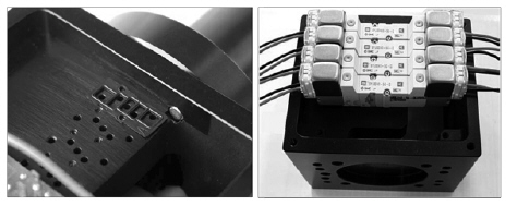
Description of the Solenoid Valves
The four solenoid valves and the covers are supplied with the Tool Connector.
Pneumatic equipment
|
Parameter |
Unit |
Value |
|---|---|---|
|
Operating pressure |
bar (psi) |
1.5…6 (21.8…87) |
|
Output at 6 bar (87 psi) from solenoid valve (Qn) |
l/min |
96 |
|
Solenoid valve opening time |
ms |
< 15 |
|
Operating frequency |
Hz |
|
|
Attachment |
– |
8x M5 |
|
Muffler connection |
– |
1x R1/8" |
You can remove the solenoid valves. The space not taken up by a solenoid valve must be covered by a plate.
Parts in the assembly set supplied:
o4x cover with seals and screws for installation.
|
NOTICE |
|
INCREASED WEAR |
|
Filter the air with a 5 μm filter. |
|
Failure to follow these instructions can result in equipment damage. |
|
|
|
FALLING HEAVY LOAD |
|
Verify in the application that the gripper is designed to hold the load with the accelerations programmed, as well as in the event of an electrical power outage or an inoperative air supply. |
|
Failure to follow these instructions can result in death, serious injury, or equipment damage. |
|
Step |
Action |
|---|---|
|
1 |
When fitting a solenoid valve, insert the screws through the solenoid valve body and then fit the sealing plate. Verify that the solenoid valve is correctly positioned. 
|
|
2 |
Screw the solenoid valve into the main body. |
|
3 |
Pressurize the Tool Connector and examine the system to verify for leaks. |
|
4 |
Make the electrical connections between the solenoid valves and the board. |
|
5 |
Verify whether the wiring is connected correctly by activating the various output switches. |
|
|
|
LOOSE WIRING OR CABLING CAUSES ELECTRIC SHOCK |
|
Verify wiring or cabling connections for correct connections. |
|
Failure to follow these instructions will result in death or serious injury. |
Description of the Tool Interface and the User Input Connections
The tool interface is on the underside of the Tool Connector.
|
NOTICE |
|
MAXIMUM PAYLOAD EXCEEDED |
|
Do not exceed the payload as defined in Mechanical Data, taking into account the additional load of the tool connector (TC), the end-effector and all the associated parts. |
|
Failure to follow these instructions can result in equipment damage. |
Equipment required:
o1x box cover
o2x box seals
o8x head screws (DIN 7984-M4x30)
o8x safety washers
o8x cable glands
You can connect up to five signals and the 0 V/24 V power supply required for the board. An additional set of 0 V/24 V power supply contacts is available.
The board has a connection dedicated to the power supply (connection terminal strip).
To connect up the power supply, remove the cable gland from the plastic cover and connect a PG7 cable. There are four passages available on the user panel.
|
Step |
Action |
|---|---|
|
1 |
Put the cable in through the cover, and then through the box joint, and connect the cable to the board connector. |
|
2 |
Pull the right-hand part of the cable into the box and fix and tighten it. |
|
3 |
Fit the cover by putting four cylindrical screws and lock washers in the cover, insert the seals, and tighten the screws. 
|


