Use the Lexium S robot for floor or wall mounting. For special applications, contact your local Schneider Electric service representative.
oWhen determining the suspension height of the robot, observe the overall height of the gripper (suction cup or other product pickups).
oFor the design of the robot frame, account for possible varying gripper heights. Possibly design the robot suspension in a height-adjustable manner.
The precision of the robot in the application is also determined by the frame. Deformations of the frame cause imprecisions on the Tool Center Point (TCP).
General Requirements Regarding the Frame
The frame must not only withstand permanently the forces and torques (refer to Mechanical Data of the respective robot), but also have sufficient stiffness so that the deformations and vibrations which occur do not lead to any major deviations on the TCP. Ensure a sufficient transverse bracing in the frame.
Note the forces and torques to be taken up by the frame during normal operation: The configuration of the robot mechanism, the speed, the acceleration, as well as the connected payload, affect the total energy, and may possibly cause damage.
NOTE: Fasten the robot with screws of property class 8.8 or greater. For more information, refer to the respective dimensional drawing in Mechanical Data.
|
|
|
CRUSHING, SHEARING, CUTTING AND IMPACT INJURY |
|
oThe robot must be operated only within an enclosure. oOpen or enter the enclosure for cleaning and maintenance purposes only. oDesign the enclosure to withstand an impact from the robot and to resist ejected parts from escaping the zone of operation. oDesign the enclosure to safely deactivate the robot as soon as a person enters the zone of operation of the robot. oAll barriers, protective doors, contact mats, light barriers, and other protective equipment, must be configured correctly and enabled whenever the robot mechanics are under power. oDefine the clearance distance to the zone of operation of the robot so the operational staff do not have access to, nor can be enclosed in, the robot mechanics zone of operation. oDesign the enclosure to account for the maximum possible travel paths of the robot; that is, the maximum path until the hardware safety system limits as well as the additional run-on paths, in case of a power interruption. |
|
Failure to follow these instructions can result in death, serious injury, or equipment damage. |
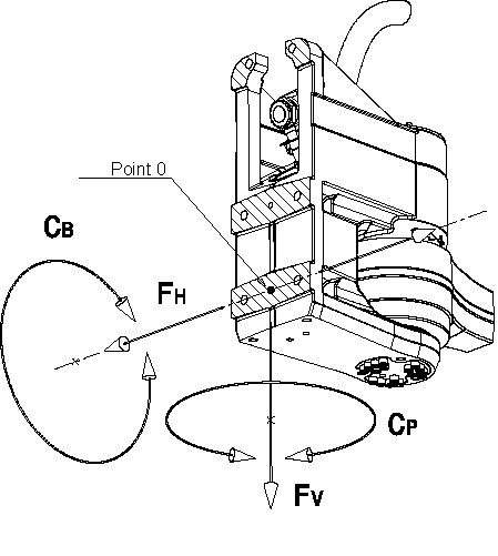
To dimension the support, take into account the maximum loads generated by the robot in motion at point 0 which are:
|
Load on holder |
Unit |
Version |
|
|---|---|---|---|
|
Floor-mounted base |
Wall-mounted console |
||
|
FV |
N (lbf) |
1455 (327) |
|
|
FH |
N (lbf) |
1750 (393) |
|
|
CB |
Nm (lbf-in) |
820 (7258) |
1100 (9736) |
|
CP |
Nm (lbf-in) |
550 (4868) |
|
Representation of Forces and Torques
Floor-mounted base version
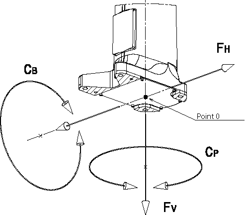
Wall-mounted console version