Here you will find the following information regarding the Lexium S robots:
oInformation about modification of ranges
oMounting flange dimensions of the base version for floor-mounting
oMounting flange dimensions of the console version for wall-mounting
|
Category |
Parameter |
Unit |
STS40 |
STS60 |
STS80 |
|---|---|---|---|---|---|
|
General data |
Position repeatability (ISO 9283) |
mm (in) |
+/-0.01 (0.0039 in) |
||
|
Range |
Range |
mm (in) |
400 (15.7) |
600 (23.6) |
800 (31.5) |
|
Internal radius |
mm (in) |
139 (5.5) |
166 (6.5) |
183 (7.2) |
|
|
Angular range (axis 1) |
– |
+/-105° |
+/-125°(1) |
+/-140° |
|
|
Angular range (axis 2) |
– |
+/-143° |
+/-150° |
+/-155° |
|
|
Stroke (axis 3) |
mm (in) |
200 (7.9) |
|||
|
Stroke (axis 3) (selectable) |
mm (in) |
400 (15.7) |
|||
|
Angular range (axis 4) with the user input/output cable |
– |
360° in either direction(2) |
|||
|
Weight |
Floor-mounted |
kg (lb) |
50.0 (110.2) |
55.4 (122) |
56.8 (125) |
|
Wall-mounted |
kg (lb) |
48.3 (106) |
53.7 (118) |
54.9 (121) |
|
|
(1) Range of +/-140° can be configured. For further information, contact your local Schneider Electric service representative. (2) Due to user input/output cables - value can be adjusted if necessary. For further information, contact your local Schneider Electric service representative. |
|||||
|
Category |
Parameter |
Unit |
STS40 |
STS60 |
STS80 |
|---|---|---|---|---|---|
|
Payload |
Rated payload at nominal speed |
kg (lb) |
2 (4.4) |
||
|
Maximum payload at reduced speed(3) |
kg (lb) |
8 (17.6) |
|||
|
Nominal inertia for axis 4 |
kg·m2 (lb·in2) |
0.05 (0.08) |
|||
|
Maximal inertias for axis 4 |
kg·m2 (lb·in2) |
0.1 (0.08) |
|||
|
Force and torque(4) |
Horizontal force (continuous / maximum) |
N (lbf) |
180 / 360 (40.5 / 81) |
130 / 260 (29 / 58) |
|
|
Vertical force (continuous / maximum) |
N (lbf) |
260 / 520 (58 / 117) |
|||
|
Axis 4 torque (continuous(5) / maximum) |
Nm (lbf-in) |
7 / 14 (62 / 124) |
|||
|
Maximum energy(6) |
Maximum energy generated by the robot in the event of an impact |
J |
150 |
220 |
370 |
|
Noise level(7) |
Noise level |
db |
72 |
79 |
79 |
|
Protection class |
IP code |
– |
IP54 |
||
|
Cleanliness class |
Cleanliness class according to standard ISO 14644-1 (with optional bellows) |
– |
6 |
||
|
(3) In all configurations and taking maximum inertias into account. (4) At the center of the tool flange. (5) Contact your local Schneider Electric service representative if axis 4 is configured as a continuous axis. (6) This energy is calculated for the nominal load, at nominal speed, with a combination of the speeds for axis 1 and axis 2 and in an extended robot position. (7) Depends on the conditions of use. When using several axes at nominal speed and nominal load, the noise level measured at a height of 1.60 m (63 in) and a distance of 1 m (39 in) from the maximum work range can reach the stated values. |
|||||
NOTE: Safe limited speed (< 250 mm/s (9.8 in/s)) can be reached with an additional implementation. This requires Lexium safety modules and a safety program. For further information, contact your local Schneider Electric service representative.
Information About Modification of Ranges
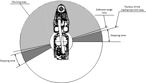
The robot is mounted in a way that provides the maximum angular amplitudes defined in mechanical data of robot STS40/60/80.
NOTE: The angular values shown in the drawings are software values and they can thus be reached.
Depending on the axes, the axis range can be limited by:
oSoftware settings
oAdjustable mechanical limit stop (available for axis 1 and axis 2)
|
|
|
DEVIATION FROM THE SAFETY REQUIREMENTS |
|
oUse the mechanical limit stops to comply with the safety requirements specified by the ISO 10218-1 standard. oDo not use software-based range limitations for safety functions in the system. |
|
Failure to follow these instructions can result in death, serious injury, or equipment damage. |
Mechanical limit stops are not included with the robot, and must be ordered separately.
The software range limit is adjusted by the nominal values.
NOTE: The software range limit can be reduced.
The axis range limitations involving mechanical systems must take the stopping distances into account.

Working area
Angular range within which the robot moves during normal operation. You can deliberately limit the range of the articulations using software, and also using adjustable mechanical limit stops.
Stopping zone (unusual operating zone)
Maximum angle necessary to stop the robot. When using the adjustable mechanical limit stop system, the stopping angle depends on the force of the impact (its maximum value is 21.5°).
|
|
|
UNINTENDED EQUIPMENT OPERATION |
|
Verify at low speed that the axis is able to move through the planned angular range, but no further, after changing a software range limit. |
|
Failure to follow these instructions can result in death, serious injury, or equipment damage. |
NOTE: When using the adjustable mechanical limit stops, verify that they are correctly placed as compared with the desired limitations, and then define the software range limit at least 2.5° less.
The Lexium S robots can be mounted at:
oFloor – in base version or
oVertical wall – in console version only
The attachment surface must be flat and metallic. Further, the attachment surface must have the strength and rigidity to support the robot and withstand the forces applied.
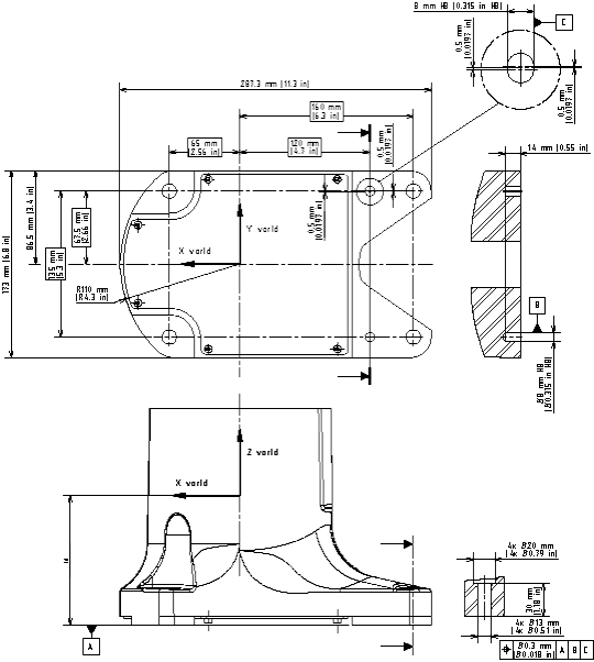
The base must be fixed in place using four M12 screws of property class 8.8 or greater, tightened to a torque of 77 Nm (682 lbf-in). You can position the robot precisely using two 8 mm (0.315 in) diameter alignment pins (not supplied). For further information, refer to the dimensional drawing of the mounting flange.
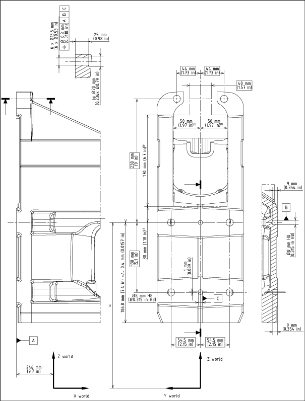
The robot can be mounted on a wall in the optional console version. The console must be fixed with six M12 screws of property class 8.8 or greater, tightened to a torque of 77 Nm (682 lbf-in). You can position the robot precisely using two 8 mm (0.315 in) diameter alignment pins (not supplied). For further information, refer to the dimensional drawing of the mounting flange.
The connection cable is supplied as standard with a straight outlet connector in base and console version.
On either robot versions (base or console), it is possible to fit either of the connector configurations. However, for the wall-mounted console version, leave an opening in the holder to enable the cable and connector to be passed through it (these openings are defined in the dimensional drawing of the mounting flange.
Mounting Flange Dimensions of the Base Version for Floor-Mounting

(1) Low position of axis 3. See the values and the figures in mechanical data of robot STS40/60/80.
Mounting Flange Dimensions of the Console Version for Wall-Mounting

(1) Dimensions of the minimum opening left in the holder to install the connection cable.
(2) Low position of axis 3. See the values and the figures in mechanical data of robot STS40/60/80.