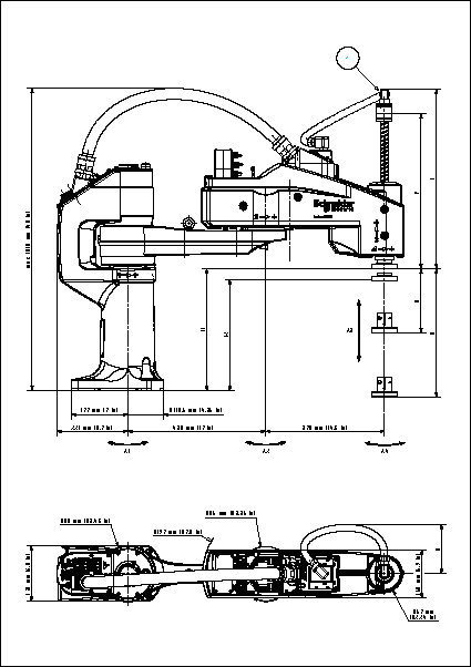
Dimensional Drawing Robot LXMSTS80F

1 User input/output cable
|
Configuration |
Parameter |
Label |
Length in mm (in) |
|
|---|---|---|---|---|
|
All |
Stroke axis 3 |
H |
200 (7.9) |
400 (15.7) |
|
Standard(1) |
Ball screw length |
P |
471 (18.5) |
671 (26.4) |
|
Height |
F1 |
380 (15) |
||
|
With bellows for the protection of the ball screw |
Ball screw length |
P |
555 (22) |
801 (31.5) |
|
Height |
F2 |
341 (13.4) |
316 (12.4) |
|
|
With user input/output cable, horizontal output configuration |
Height of the user installation |
I |
588 (23) |
782 (31) |
|
Overall measurements of the user installation |
B |
190 (7.5) |
200 (7.9) |
|
|
With user input/output cable, horizontal output configuration and bellows |
Height of the user installation |
I |
627 (24.7) |
846 (33) |
|
Overall measurements of the user installation |
B |
190 (7.5) |
200 (7.9) |
|
|
(1) The subsequent installation or replacement of variants (for example bellow) in a standard configuration influences the length. This leads to a zero shift in the height. |
||||
NOTE: You can change the orientation of the user input/output cable to the right-hand side.
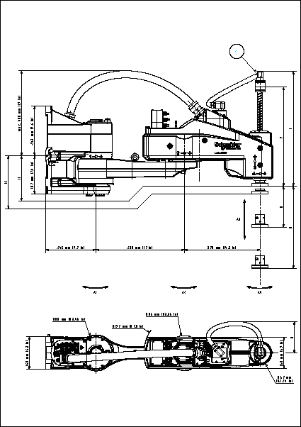
Dimensional Drawing Robot LXMSTS80W with Console

1 User input/output cable
|
Configuration |
Parameter |
Label |
Length in mm (in) |
|
|---|---|---|---|---|
|
All |
Stroke axis 3 |
H |
200 (7.9) |
400 (15.7) |
|
Standard(1) |
Ball screw length |
P |
471 (18.5) |
671 (26.4) |
|
Height |
F1 |
148 (5.8) |
||
|
With bellows for the protection of the ball screw |
Ball screw length |
P |
555 (22) |
801 (31.5) |
|
Height |
F2 |
187 (7.4) |
212 (8.3) |
|
|
With user input/output cable, horizontal output configuration |
Height of the user installation |
I |
588 (23) |
782 (31) |
|
Overall measurements of the user installation |
B |
190 (7.5) |
200 (7.9) |
|
|
With user input/output cable, horizontal output configuration and bellows |
Height of the user installation |
I |
627 (24.7) |
846 (33) |
|
Overall measurements of the user installation |
B |
190 (7.5) |
200 (7.9) |
|
|
(1) The subsequent installation or replacement of variants (for example bellow) in a standard configuration influences the length. This leads to a zero shift in the height. |
||||
NOTE: You can change the orientation of the user input/output cable to the right-hand side.

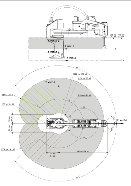
(1) 360° in either direction due to user input/output - value can be adjusted if necessary. For further information, contact your local Schneider Electric service representative.
NOTE: The orange and green circles represent the reduced working area in relation to the arm configuration (left or right).