Risks arising from the robot have been reduced. However a residual risk remains since the robot is moved and operated with electrical voltage and electrical currents.
If activities involve residual risks, a safety message is made at the appropriate points. This includes potential hazards that may arise, their possible consequences, and describes preventive measures to avoid the hazards.
|
|
|
ELECTRIC SHOCK, EXPLOSION, OR ARC FLASH |
|
oDisconnect all power from all equipment including connected devices prior to removing any covers or doors, or installing or removing any accessories, hardware, cables, or wires except under the specific conditions specified in the appropriate hardware guide for this equipment. oAlways use a properly rated voltage sensing device to confirm the power is off where and when indicated. oOperate electrical components only with a connected protective ground (earth) cable. oVerify the secure connection of the protective ground (earth) cable to all electrical devices to ensure that connection complies with the connection diagram. oDo not touch the electrical connection points of the components when the module is energized. oProvide protection against indirect contact (EN 50178). oInsulate any unused conductors on both ends of the motor cable. |
|
Failure to follow these instructions will result in death or serious injury. |
The robot mechanics, apart from the motor, are not supplied with external brakes nor an emergency stop switch to engage any external brakes.
|
|
|
ENTRAPMENT BY ROBOT MECHANICS |
|
oProvide means for ensuring that the motors can be put into a voltage-free state with any internal holding brake or external service brake released. oMake available those means to allow one person to manually move the robot within reach of the zone of operation. |
|
Failure to follow these instructions can result in death, serious injury, or equipment damage. |
The opening of the motor holding brakes may cause the robot to sag.
|
|
|
SAGGING OF THE ROBOT |
|
Ensure that the release of the motor brakes poses no subsequent risks in the zone of operation. |
|
Failure to follow these instructions can result in death, serious injury, or equipment damage. |
NOTE: Provide separation devices for all infeed energies. It must be possible to secure the separation devices in de-energized position, for example, by locking.
|
|
|
CRUSHING, SHEARING, CUTTING AND HITTING DURING HANDLING |
|
oObserve the general construction and safety regulations for handling and assembly. oUse appropriate mounting and transport equipment and use appropriate tools. oPrevent clamping and crushing by taking appropriate precautions. oCover edges and angles to protect against cutting damage. oWear suitable protective clothing (for example, protective goggles, protective boots, protective gloves). |
|
Failure to follow these instructions can result in death, serious injury, or equipment damage. |
Parts of the mechanics can move at high speeds. In such cases, the payload weight, additionally installed gripper, and shifts in the center of gravity of the moving parts contribute to the total energy of the forces generated.
Motion sequences can occur when operating with robot mechanics, which allow operational staff to make misjudgments. For safety considerations (according to EN ISO 13849-1), consider the controller and the brakes as non-safety-related elements. Ensure that necessary protective measures are implemented.
The safety standards and directives for the respective country where the equipment is in use define which protective measures are appropriate. Additionally, the system engineer who is responsible for the integration of the robot mechanics must evaluate which measures have to be taken.
NOTE: The configuration of the robot mechanics, the Tool Center Point (TCP) velocity, as well as the additional payload have an effect on the total energy, which can potentially be a source of damage and injury.
|
|
|
CRUSHING, SHEARING, CUTTING AND IMPACT INJURY |
|
oThe robot must be operated only within an enclosure. oOpen or enter the enclosure for cleaning and maintenance purposes only. oDesign the enclosure to withstand an impact from the robot and to resist ejected parts from escaping the zone of operation. oDesign the enclosure to safely deactivate the robot as soon as a person enters the zone of operation of the robot. oAll barriers, protective doors, contact mats, light barriers, and other protective equipment, must be configured correctly and enabled whenever the robot mechanics are under power. oDefine the clearance distance to the zone of operation of the robot so the operational staff do not have access to, nor can be enclosed in, the robot mechanics zone of operation. oDesign the enclosure to account for the maximum possible travel paths of the robot; that is, the maximum path until the hardware safety system limits as well as the additional run-on paths, in case of a power interruption. |
|
Failure to follow these instructions can result in death, serious injury, or equipment damage. |
For detailed information about travel path and power loss, refer to Run-on Motions of the Robot for Risk Analysis.
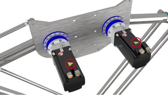
The metal surfaces of the robot may exceed 85 °C (185 °F) during operation.
The following figure presents the hot surface labels on the robot.

|
|
|
HOT SURFACES |
|
oAvoid unprotected contact with hot surfaces. oDo not allow flammable or heat-sensitive parts in the immediate vicinity of hot surfaces. oVerify that the heat dissipation is sufficient by performing a test run under maximum load conditions. |
|
Failure to follow these instructions can result in death, serious injury, or equipment damage. |
There can be different sources of hazardous movements:
oNo or incorrect calibration of the drive
oWiring or cabling errors
oErrors in the application program
oComponent errors
oError in the measured value and signal transmitter
NOTE: Provide for personal safety by primary equipment monitoring or measures. Do not rely only on the internal monitoring of the drive components. Adapt the monitoring or other arrangements and measures to the specific conditions of the installation in accordance with a hazard and risk analysis.
|
|
|
UNAVAILABLE OR INADEQUATE PROTECTION DEVICE(S) |
|
oPrevent entry to a zone of operation with, for example, protective fencing, mesh guards, protective coverings, or light barriers. oDimension the protective devices properly and do not remove or modify them. oDo not make any modifications that can degrade, incapacitate, or in any way invalidate protection devices. oBring the drives and the motors they control to a stop before accessing the drives or entering the zone of operation. oProtect existing workstations and operating terminals against unauthorized operation. oPosition emergency stop switches so that they are easily accessible and can be reached quickly. oValidate the functionality of emergency stop equipment before start-up and during maintenance periods. oPrevent unintentional start-up by disconnecting the power connection of the drives using the emergency stop circuit or using an appropriate lock-out tag-out sequence. oValidate the system and installation before the initial start-up. oAvoid operating high-frequency, remote control, and radio devices close to the system electronics and their feed lines. oPerform, if necessary, a special electromagnetic compatibility (EMC) verification of the system. |
|
Failure to follow these instructions will result in death or serious injury. |
Drive systems may perform unanticipated movements because of incorrect wiring, incorrect settings, incorrect data, or other errors.
|
|
|
UNINTENDED MOVEMENT OR MACHINE OPERATION |
|
oCarefully install the wiring in accordance with EMC standards. oDo not operate the robot with undetermined settings and data. oPerform comprehensive commissioning tests that include verification of configuration settings and data that determine position and movement. |
|
Failure to follow these instructions can result in death, serious injury, or equipment damage. |
The noise level of the mechanics depends on the basic cycle and the payload, as well as on further application-specific accessory parts. Be aware of the fact that noise emissions multiply when several mechanics are in use at the same time. If noise emissions reach a value of more than 70 dBA, wear hearing protection.
|
|
|
NOISE EMISSIONS OF THE ROBOT MECHANICS |
|
oWear hearing protection in accordance with the locally applicable regulations. oAttach a sign on the robot mechanics if the noise emissions reach an excessive value. |
|
Failure to follow these instructions can result in injury or equipment damage. |
NOTE: Attach the following symbol where it can easily be seen on the robot mechanics.

Some small amounts of lubricant emissions are to be expected over time. However, excessive lubricant emissions on or at the gearbox may be an indication of a damaged robot.
|
NOTICE |
|
INOPERABLE EQUIPMENT INDICATED BY GEARBOX LUBRICANT EMISSIONS |
|
oVerify the mechanics before, during, and after use. oShut down the mechanics immediately if lubricant emissions appear on the robot mechanics. |
|
Failure to follow these instructions can result in equipment damage. |
The robot is capable of suspending heavy loads.
|
|
|
FALLING LOADS |
|
Do not stand under hanging loads. |
|
Failure to follow these instructions can result in death, serious injury, or equipment damage. |
If different customer end products are transported by the robot mechanics, then the product pickup must be modified accordingly. For this reason, you can mount different product pickups (gripper mounting) to the flange. In doing so, ensure that the articulation movement is not restricted and/or that no motion errors can result from the modifications. Attachments and rebuilds must not influence the operation of the protective devices in any way and all EMERGENCY STOP buttons must be accessible and operational at all times.
|
|
|
UNINTENDED MACHINE OPERATION |
|
oDo not drill into or modify the articulated arms. oDo not modify the cable set. oDo not modify the mounting plate. oDo not modify the components of movable mechanics. |
|
Failure to follow these instructions can result in death, serious injury, or equipment damage. |
Options for Moving the Robot Without Drive Energy
The robot mechanics are not equipped with a security frame.
NOTE: Take appropriate security measures concerning the specific use before operating the robot.
|
|
|
SAGGING OF THE ROBOT |
|
Ensure that the release of the motor brakes poses no subsequent risks in the zone of operation. |
|
Failure to follow these instructions can result in death, serious injury, or equipment damage. |
If the equipment is with power, perform the following steps:
|
Step |
Action |
|---|---|
|
1 |
Switch the robot into a torque-free state. |
|
2 |
Manually hold the robot in position. |
|
3 |
Open the motor brakes. NOTE: The function for opening the brakes as well as for torque-free switching of the motors is not included within the scope of supply. Implement the same as a component part of the design of the electrical equipment. |
|
4 |
Manually move the robot. NOTE: A greater force could be necessary because the motor and the gearbox may pose resistance to movement. |
|
5 |
Close the brakes. |
If the equipment is without power, perform the following steps:
|
Step |
Action |
|---|---|
|
1 |
Disconnect the motor cables from the motors. |
|
2 |
Apply an external 24 V supply to the appropriate connection points to release the motor brakes if necessary. |
|
3 |
Release the external brakes engaged by the functional safety system of the robot. |
|
4 |
Manually move the robot. NOTE: A greater force could be necessary because the motor and the gearbox may pose resistance to movement. |
|
5 |
Remove the external current to close the brakes. |
|
6 |
Reconnect the motor cables to the motor. |