Adding a New MultiBelt Equipment Module
This chapter explains how to integrate a MultiBelt equipment module into a default PacDrive template.
The instructions refer to the project: PD_Demoproject_MultiBeltModule_V2.0.4.0.project (or higher) and the PD_Demoproject_Template_Full_Demo_V2.0.13.0.project (or higher).
Requirement:
PD_Demoproject_Template_Full_Demo_V2.0.13.0.project as template, controller firmware version: 1.35.1.9 (or higher).
oIntegrate necessary libraries
Integrate the libraries of the PD_MultiBeltModule 1.0.3.0 equipment module (or higher)
oas well as the libraries of the technology POUs PD_MultiBelt 1.1.5.0 (or higher). All further needed libraries are already part of it.
oPrepare the PLC configuration.
Define the required drives and logical encoders for the MultiBelt. The mechanical design of the MultiBelt determines which elements are required. An axis must be created for each train and a logical encoder for each indexed station if the start is performed via a TP. Also see example of an Init_MultiBeltModule action
In the following example, a MultiBelt is integrated with three stations and four trains. The names of the objects follow the name conventions of the PD templates.
In the MultiBelt demo project, the designation for the axes of the trains is DRV_Train1 to DRV_Train4 and the designation of the logical encoder for the loading station is LE_StartDelayStation1. The designation of the logical encoder for the unloading station is LE_Master.
oVariable declaration
The following variables must be created in the declaration section of the node, in which the MultiBeltModule should be located. In the demo project, the module is located in the SR_CharlyModule module.
// MultiBelt Variables
stMultiBeltItf : MTBM.ST_ModuleInterface;
fbMultiBeltModule : MTBM.FB_MultiBeltModule;
fbMultiBeltModuleCtrl : MTBM.FB_MultiBeltModuleController;
// Start Simulation
fbSimStation1 : MTBM.FB_StartSimulation;
fbSimStation2 : MTBM.FB_StartSimulation;
stSimStation1 : MTBM.ST_StartSimulationParameter;
stSimStation2 : MTBM.ST_StartSimulationParameter;
xStartSimStation1 : BOOL;
xNotEquidistandStation1 : BOOL;
xNotEquidistandGroupsStation1 : BOOL;
xNotRandomStation1 : BOOL;
xNorRandomGroupsStation1 : BOOL;
xStartSimStation2 : BOOL;
xNotEquidistandStation2 : BOOL;
xNotEquidistandGroupsStation2 : BOOL;
xNotRandomStation2 : BOOL;
xNorRandomGroupsStation2 : BOOL;
rtrigStation1 : R_TRIG;
rtrigStation2 : R_TRIG;
oCreate constant
The c_udiNumberOfSubModules constant is increased by one in the declaration section of the node (3->4).
A constant c_udiMultiBelt: UDINT:= 4; is created.
oCall up FB_MultiBeltModuleController and FB_MultiBeltModule
fbMultiBeltModuleCtrl and fbMultiBeltModule must be called up in the SubModules action of the node. It is important to call up the controller before the module.
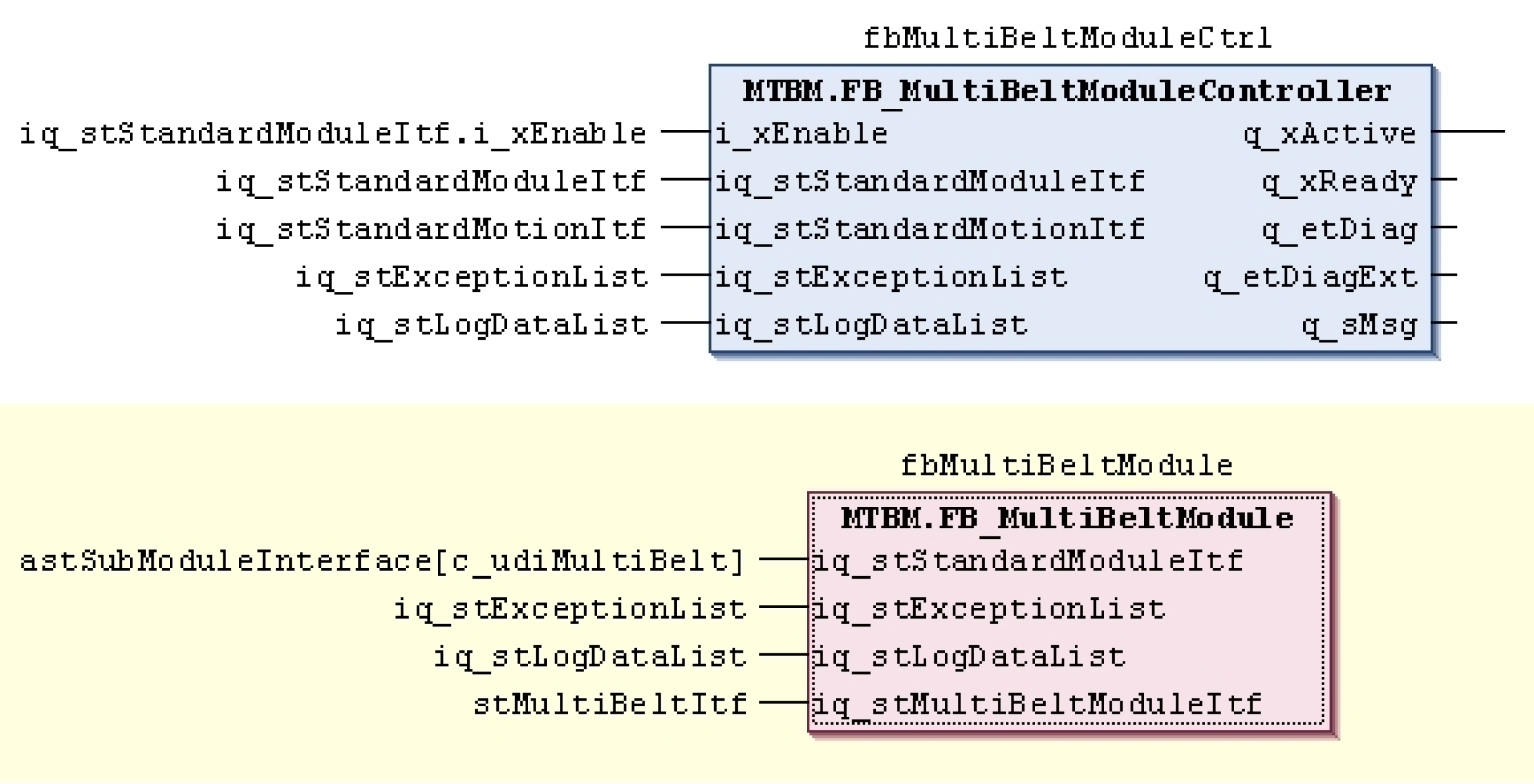
oConnect the controller and the module as shown in the figure above.
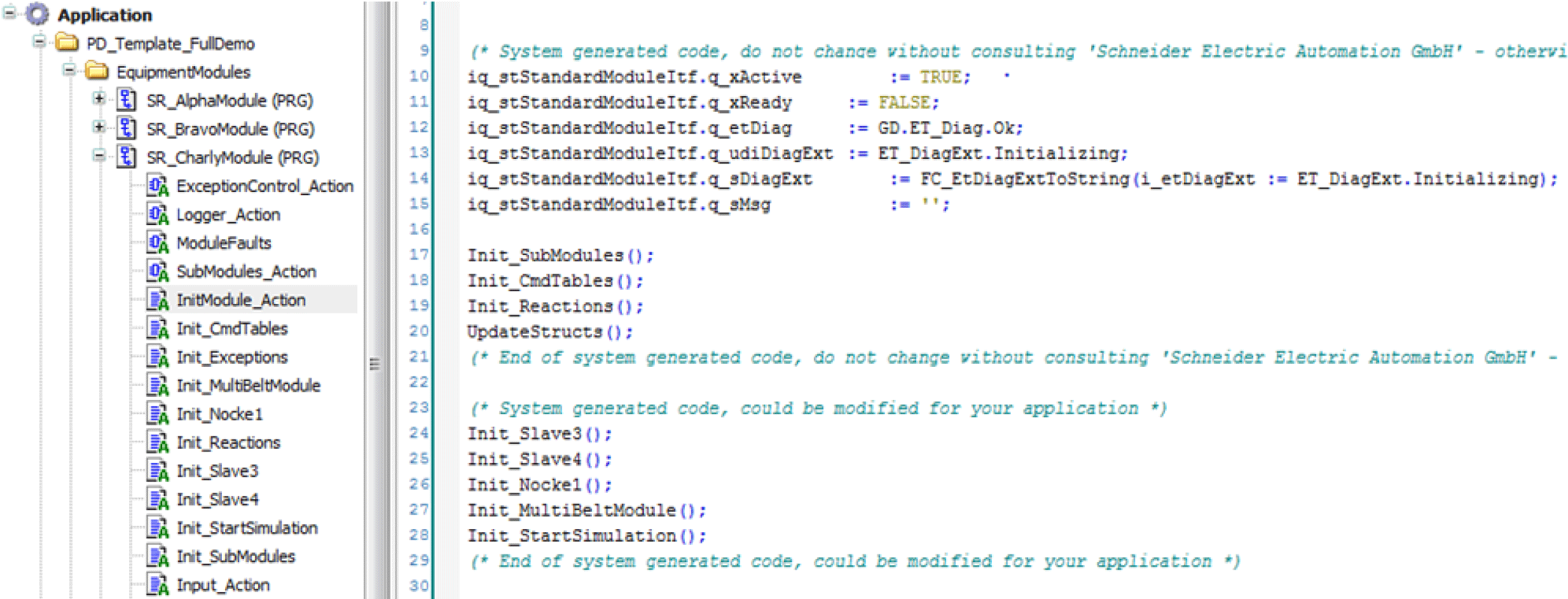
oInsert an action with the name Init_MultiBeltModule into the node of the module and call it up in the InitModule_Action step.
An example for this action can be found in the chapter Example of an Init_MultiBeltModule action.
oAdapt the table commands in the Init_CmdTables action of the node.
For this purpose, use the commands of the ENUM MTBM.ET_Cmd. An example for a table is located in the chapter Example of a Cmd table.
oCall up the MTBM.FC_UpdateAddInterfaceStruct function in the UpdateStructs action of the node. You can orient yourself using the example FC_UpdateExampleLeafModuleAddInterfaceStruct.
MTBM.FC_UpdateAddInterfaceStruct(
i_pdwSubModuleAddInterfaces:= ADR(adwSubModuleAddInterfaces),
i_udiSubModuleConstant:= c_udiMultiBelt,
iq_stMultiBeltModuleItf:= stMultiBeltItf,
q_etDiag=> etDiag,
q_etDiagExt=> etDiagExt);
oInsert the following persistent variables into the folder GlobaleVariable/RestoreAxisPosition:
lrLoadPosRetainStation1: LREAL;
lrLoadPosRetainStation2: LREAL;
lrLoadPosRetainStation3: LREAL;
lrLoadPosRetainStation4: LREAL;
lrLoadPosRetainStation5: LREAL;
lrLoadPosRetainStation6: LREAL;
lrLoadPosRetainStation7: LREAL;
lrLoadPosRetainStation8: LREAL;
astRestoreTrain: ARRAY[1..MTB.Gc_uiMaxNumberOfBelts] OF PDL.ST_HomeSetPos;
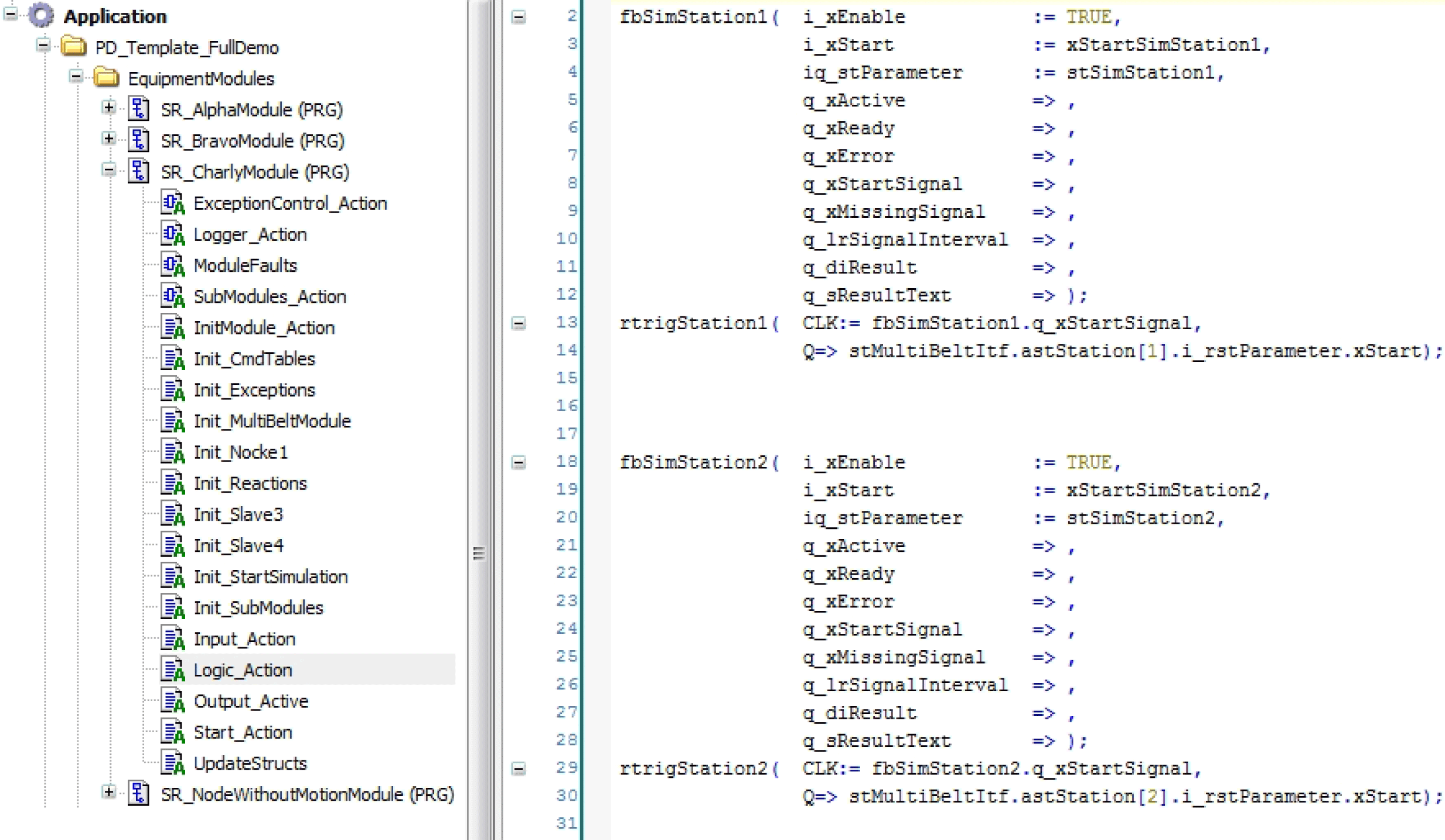
oCreate an action with the name Init_StartSimulation in the SR_CharlyModule.
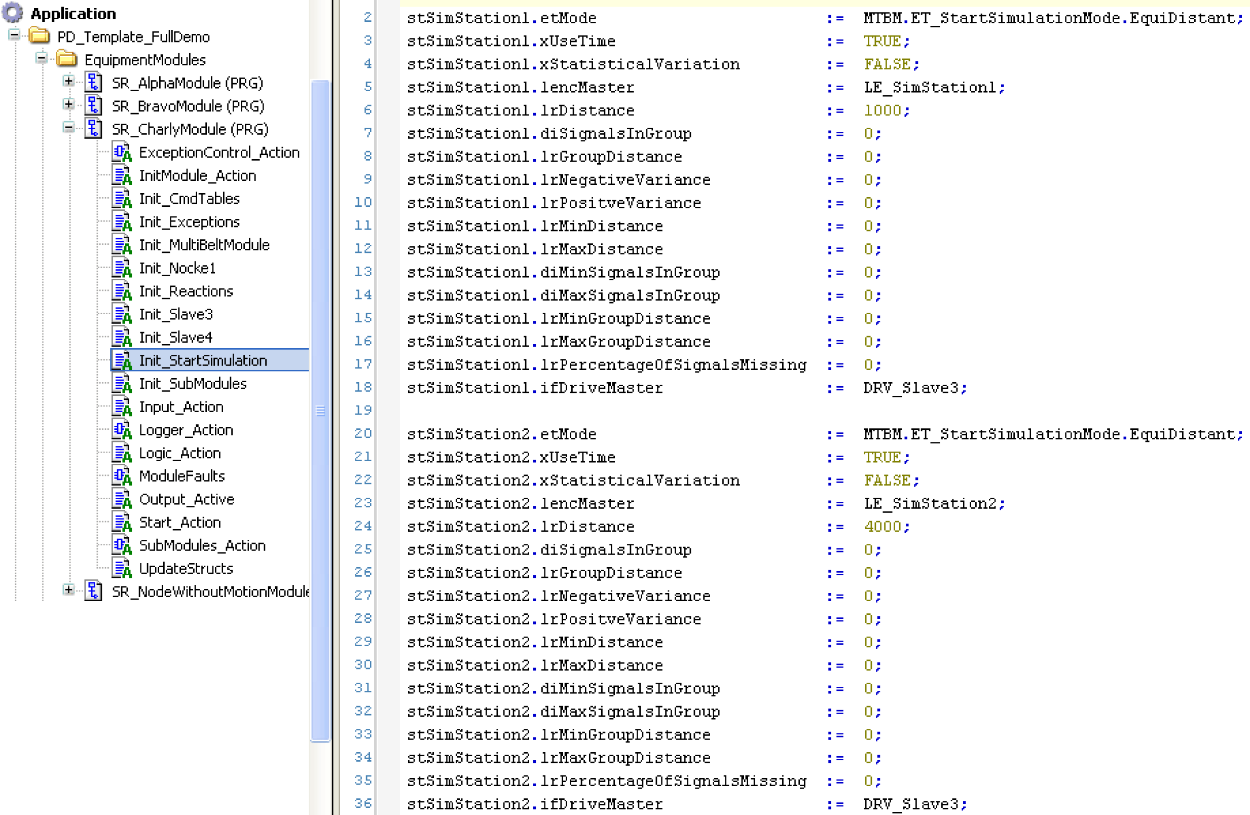
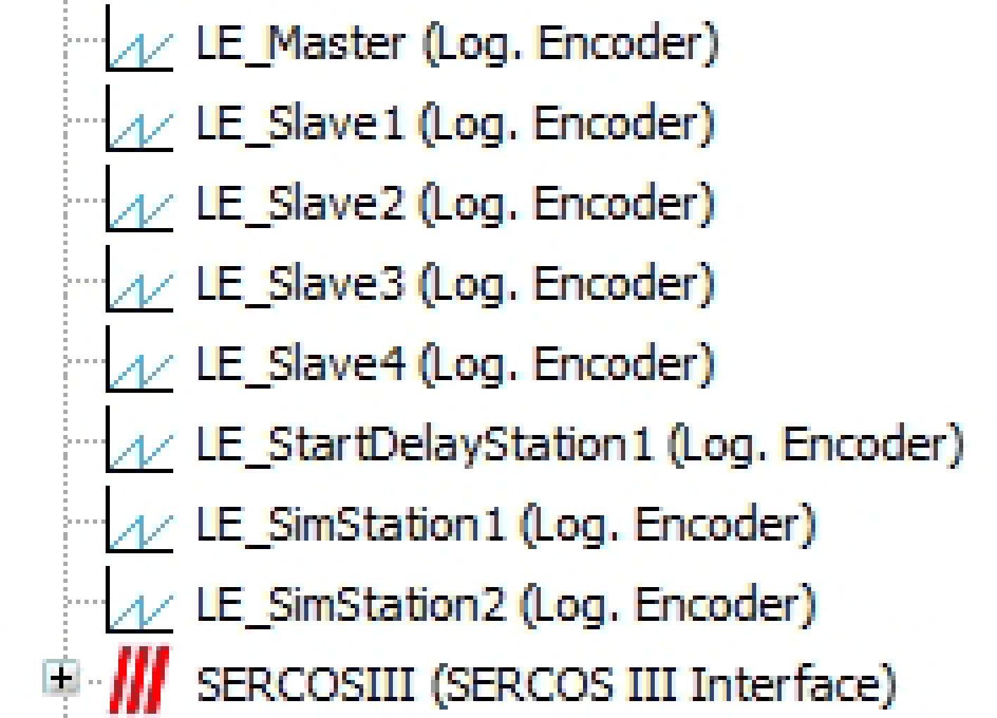
oCreate the two logic encoders LE_SimStation1 and LE_SimStation2.
oThen, call up LE_SimStation1 and LE_SimStation2 in the action InitModule_Action.
oCall up the start simulation in the action Logic_Action.
Integration into Template Visualization
oIntegrate MTBM.FB_MultiBeltModuleVisController
Insert the following line in the declaration section of SR_VisControl():
vpq_xDisplaySetJogTargetButton: BOOL;
vpiq_fbMultiBeltVisController: MTBM.FB_ModuleVisController;
oInsert the following code in the action SR_VisControl.ModuleVisController:
vpiq_fbMultiBeltVisController(
i_xEnable:= vpq_xDoEnable,
i_pstMachineStandardItf:= ADR(SR_MainMachine.stMachineInterface),
i_pstCurrentStandardItf:= pstCurrent,
i_dwCurrentAddItf:= dwCurrentAddInterface,
i_xUpdateData:= xUpdateForOtherFBs,
i_udiCurrentJogTarget:= G_udiManualModuleSelect,
iq_stExceptionList:= G_stExceptionList,
iq_stLogDataList:= G_stLogDataList,
q_udiSetAsCurrentModule=> udiSetAsCurrentModule,
q_udiSetAsJogTarget=> udiSetAsJogTarget);
SetCurrentModule();
oCopy all visualizations from the folder Visualization/MultiBeltModule (Vis_MultiBeltModule, Vis_MultiBeltModule_StationFeedback, Vis_MultiBeltModule_StationParameter, VIS_MultibeltModule_Train, Vis_MultiBeltModule_Simulation as well as the Vis_MultiBeltModule_Service) from the demo project to the current project.
oIf not already available, copy the FR_OtherModuleTypes frame from the Visualization/FramesProject folder from the demo project to the current project.
oCreate an instance of the function block FB_MultiBeltDiagSource in the declaration section of the program "SR_Diagnostics".
fbMultiBeltModuleDiagSource: MTBM.FB_MultiBeltDiagSource;
oIn the program section of "SR_Diagnostics", call up the instance of the diagnostic source.
