This topic contains the following subtopics:
oUse
If devices are exchanged, whose Device addressing has been made via the Identification mode -> Device serial number (SerialNumberController / 0, also see IdentificationMode and Device addressing) on this, it comes to Sercos phase start-up errors because the old and the new device inevitably has different serial numbers.
Even if the Device addressing has been performed via Identification mode-> Application type (ApplicationType / 3 ) or Identification mode -> Sercos address (SercosAddress / 4 ), Sercos phase start-up errors may occur.
In these cases, the FDR display mechanism shall give you the possibility to manually access the assignment between logical devices in the PLC Configuration (Logic Builder) and the physical connected devices.
After you have acknowledged the assignment of an exchanged device via the controller display,
oThe serial number of the physically connected device is copied into the parameter ConfiguredSerialNumber of the logical device in the PLC configuration or
oThe application type or the Sercos address is written via the Sercos bus onto the respective device.
Even after a restart these changes are still saved. This means, if the controller is restarted again after a successful device assignment, the parameters changed via the FDR display mechanism still exist. Also see chapter "Behavior after repeated download".
The permanently saved information is stored on the flash disk card of the PacDrive LMC x00C or the PacDrive LMC x01C (device serial number, also see "FC_SysSaveParameter" and "FC_SysSaveParByLogAddr") or on the respective device (application type/Sercos address).
After, you assigned the exchanged devices via the controller display the assignment is checked again during the Sercos phase start-up.
To be able to make an assignment between the logical devices in the PLC configuration (Logic Builder) and the physical connected devices via the controller display, the following requirements have to be fulfilled:
oThe device addressing was performed in one of the following ways:
oIdentification mode -> Device number (SerialNumberController / 0, also see IdentificationMode and Device addressing)
oIdentification mode -> Application type (ApplicationType / 3 )
oIdentification mode -> Sercos address (SercosAddress / 4)
The value SerialNumberMotor / 1 is not supported for this parameter.
oThe parameter FDRConfirmationMode of the controller was set to the value by display / 0 (= default).
NOTE: We suggest writing down the device serial number of the new device before the installation because you need it later on for the assignment via the display.
The following parameters of the controller have influence on the FDR display mechanism:
|
Parameter |
Description |
|---|---|
|
Determines if and when the Fast Device Replacement is performed. |
|
|
This parameter is set to executed/3 during the runtime of the FDR display mechanism.Afterwards the parameter is set to inactive/0. |
|
|
The value by display / 0 of this parameter shows that the FDR display mechanism is activated. The value by parameter / 1 of this parameter shows that the FDR display mechanism is deactivated. In this case, oa serial number that is changing has to be written manually via an application into the parameter ConfiguredSerialNumber of the exchanged device oor the application type / the Sercos address must be written manually onto the exchanged device (also see ApplicationType / 3 and SercosAddress / 4). |
Error during the manual device assignment
If 2 or more devices of the same type (or a Double drive) are exchanged, it is possible that you may make a mistake by the manual assignment of the logical devices to the physical connected devices.
|
|
|
Unanticipated Operating State of the Device |
|
oMake sure that the assignment of the logical devices to the physical connected devices equates exactly the device assignment before the device exchange. oBefore commissioning the system, you have to check that the programmed logic controls the correct physical drives. |
|
Failure to follow these instructions can result in death, serious injury, or equipment damage. |
The FDR display mechanism does not consider the device type of physical devices.
NOTE: If the logical device type does not equate the assigned physical device type, then a device assignment with the FDR display mechanism is possible but it leads to an error during the Sercos phase up (8501 SERCOS slave not found). If FDRStartMode is set to the value “phase up / 2”, then the FDR display mechanism is restarted.
If the requirements are fulfilled (see chapter “Requirements”) and you are exchanging a device, then the controller display automatically shows the start picture of the FDR display mechanism.
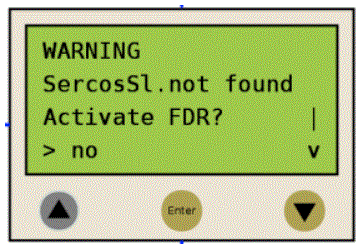
oYou can exit the FDR display mechanism with the "Enter" key (if the "Arrow pointing right" is on "No").
-> The FDR display mechanism is ended.
oYou can also switch to "Yes" with the "Arrow pointing down" key ("Arrow pointing right" on "Yes") and then confirm the "Yes" with "Enter.
-> Now you can navigate through the menu like described in the chapter "Controller display". Also see chapter "Application"
If no button is pressed at the display for 5 minutes, the FDR display mechanism is terminated (timeout = 5 minutes). The system then behaves as if you have terminated the FDR mechanism as described above. If you press a display button within the 5 minutes, the time for the timeout is reset.
Behavior After Repeated Download
If after the FDR display mechanism a download of a project is made, then the saved changes of the parameter ConfiguredSerialNumber are reset and set to the values that are saved in the project that was downloaded.For devices that are identified via Identification mode -> Device number (SerialNumberController / 0) and were allocated via FDR, the system acts as if the FDR display mechanism had not been performed.
When the FDR display mechanism is active, the controller display shows the corresponding menu.
The following describes the menu in general. Further information can be found in the chapter "Application".
|
Arrow key |
Description |
|
|---|---|---|

|

|
If up/down arrows are displayed at the right menu edge, you can scroll up and down using these arrow keys. Scrolling starts only after the "right arrow" is displayed at the lower or upper menu edge. If the "right arrow" is displayed in a line in between, you can move it using the "up/down arrow" keys. |

|

|
|

|
- |
The command that is in the line that is marked with the "Arrow pointing right" can be confirmed/executed with the "Enter" key. |

|
- |
|
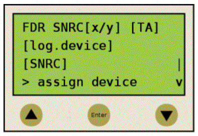
In the following example, "FDR SNRC" stands for addressing a device via the device serial number. Instead of "FDR SNRC", the "FDR ATYP" (for application type) or "FDR SADR" (for Sercos address) can also be used.
|
Placeholders |
Descriptions |
|---|---|
|
[x/y] |
Number of the logical device that currently has to be processed (x) and the total number of the devices that have to be assigned (y). If, for example 20 devices cannot be assigned and you already assigned 11 devices via the FDR display mechanism, then ”12/20” is displayed. If this line (for example, FDR SNRC[x/y] [TA]) contains more than 18 characters, the first 16 characters are followed by "..". Via the menu command "Details" you can switch to a display mode that shows the complete row (see below). |
|
[TA] |
Topological address of the physical device that is currently displayed. |
|
[log.device] |
Name of the logical device in the PLC configuration (Logic Builder), that shall be assigned to the physical device at the topological address [TA]. If the device name has more than 18 characters, then the first 16 characters of the device name are followed by "..". Via the menu command "Details" you can switch to a display mode that shows the logical device name completely (see below). |
|
[SNRC] |
Name of the logical device in the PLC configuration (Logic Builder), that shall be assigned to the physical device at the topological address [TA]. If the device name has more than 18 characters, then the first 16 characters of the device name are followed by "..". Via the menu command "Details" you can switch to a display mode that shows the logical device name completely (see below). |
NOTE: Devices that were assigned via the menu item/command "Assign device" (see below) cannot be removed again via a menu item/command.
|
Menu command / Command |
Description |
|---|---|
|
Assign device |
With this command, you confirm the assignment between the logical device [log.device] and the physical device at the topological address [TA]. oIn the case of Identification mode > Device serial number, the serial number of the physical device is copied to the parameter ConfiguredSerialNumber of the logical device. oIn the case of Identification mode > Application type, the application type is written to the respective device via the Sercos bus. oIn the case of Identification mode > Sercos address, the Sercos address is written to the respective device via the Sercos bus. After assigning a device the x (see placeholder [x/y]) is increased. If no other devices without an assignment are existent, then the mechanism is completed and the Sercos phase start-up continues. |
|
Next phys. |
With this command, the next physical device to the logical device (x) that currently has to be processed is displayed. |
|
Details |
With this command, it is possible to switch to a display mode that displays the complete lines (multi-line). This is helpful if in the standard view lines cannot be displayed completely (see above).For a logical device, a maximum of 40 characters can be displayed. |
|
Back |
With this command, it is possible to switch back to the standard view (max. 16 characters followed by ".." Are displayed). |
|
Exit FDR |
With this command, the FDR display mechanism is canceled. The cancelation has to be confirmed once again ("Really exit?" -> "Exit FDR"). |
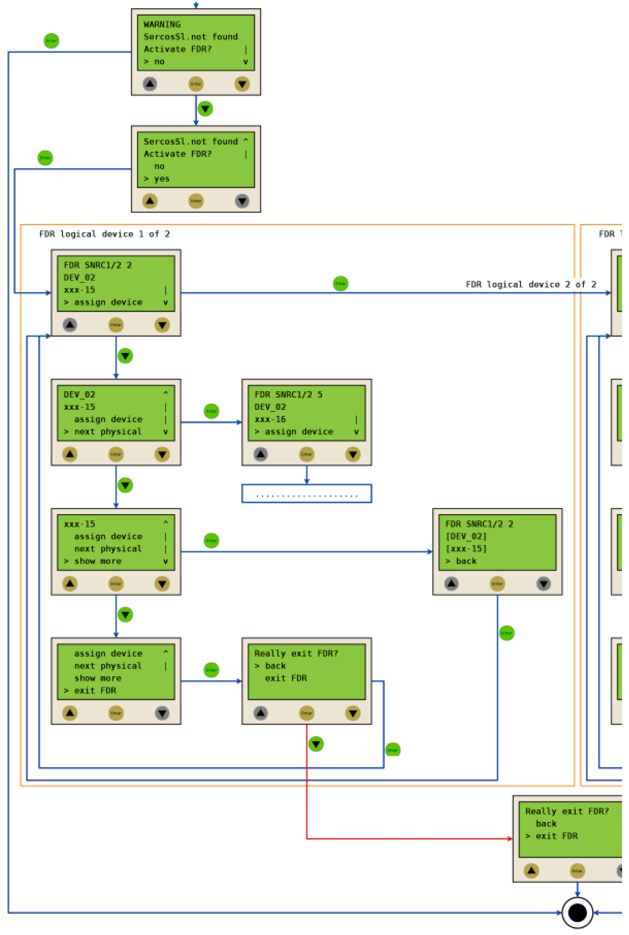
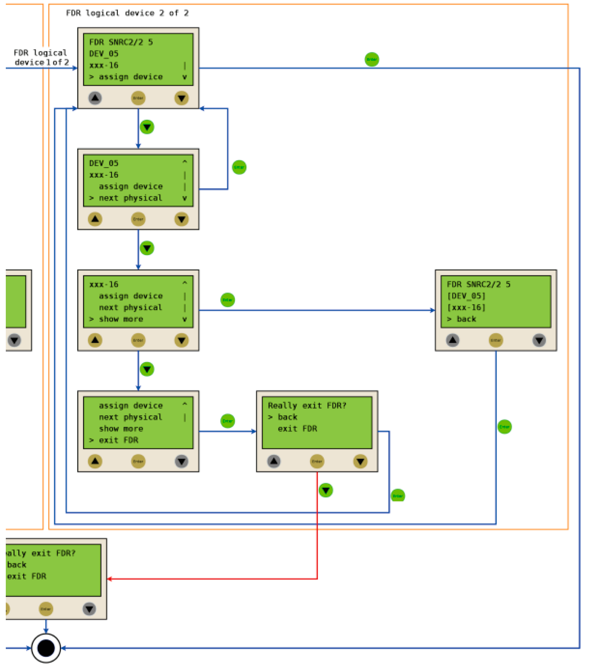
The following example shows a typical application for the FDR display mechanism.
Starting conditions
For the displayed example the following applies:
oThe devices are ok.
oThe Sercos bus is started up.
oFor the devices the Device addressing via the Identification mode > Device serial number was made (parameter SerialNumberController / 0).
oThe parameter FDRConfirmationMode of the controller was set to the value by Display / 0.
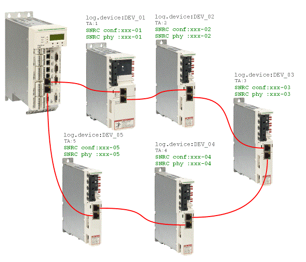
Device replacement
The following devices have to be replaced because of maintenance:
oThe device at the topology address 2 (TA:2) with the logical device name DEV_02 and the serial number SNRC phy: xxx-02 has to be replaced by the new device that has the serial number SNRC phy: xxx-15.
oThe device at the topology address 5 (TA:5) with the logical device name DEV_05 and the serial number SNRC phy xxx-05 has to be replaced by the new device that has the serial number SNRC phy xxx-16.
After the device replacement
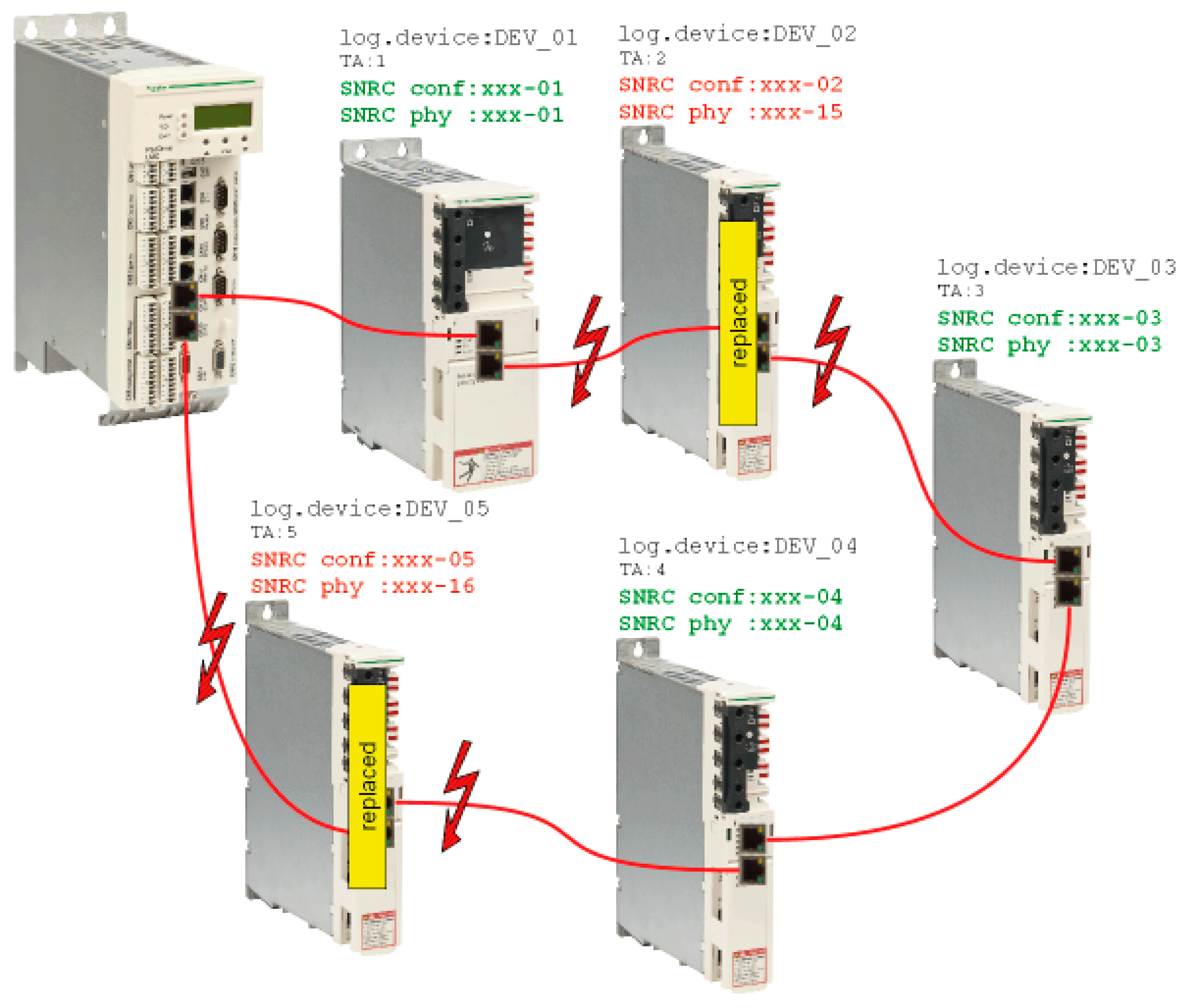
After the physical exchange of the devices the machine has to be restarted again. So that the FDR display mechanism starts the parameter FDRStartMode has to be set to Start/1 or Phase start-up/2 and the parameter FDRConfirmationMode to by Display / 0.
Now the FDR display mechanism has to find the correct assignment of the two logical devices DEV_02 and DEV_05 to the new physically connected devices at topology address 2 and 5.
Process
The FDR display mechanism checks all the logical devices one after another which would trigger the error 8501 SERCOS slave not found during the SERCOS phase start-up. Afterwards, to the respective logical device all the physical devices are checked until one device is acknowledged.
Due to space constraints, the sequence for device 1 and device 2 is displayed one beneath the other.
