SLS1 to SLS4 - four Safely Limited Speed functions
General function description
A Safely Limited Speed function causes the controlled deceleration of a motor to a defined target speed. The drive is decelerated until a defined final limited speed has been achieved which is then monitored. SLS therefore prevents the motor to exceed the defined limited speed.
The function block provides four separate SLS monitoring functions: SLS1 to SLS4. They work identically but can be parameterized and requested independent of each other, thus enabling four different speeds to be monitored.
NOTE:
If several SLS functions are requested at the same time, SLS1 has the highest and SLS4 the lowest priority.
When requesting several SLS functions, you must parameterize the slowest target speed v2 for the SLS with the highest priority:
v2(SLS1) <= v2(SLS2) <= v2(SLS3) <= v2(SLS4)
Exception: any v2 value = 0 is ignored and does not result in an error.
Other configurations will be considered a configuration error and the module will not attain operational state.
Example: the following configuration is valid:
v2(SLS1) = 600, v2(SLS2) = 600, v2(SLS3) = 800 v2(SLS4) = 0
Monitoring by the safety-related FB/Safety Module
The monitoring behavior by the function block depends on the parameterization of the Safety Module:
If ramp monitoring is deactivated, monitoring is passive until the t2 time interval has elapsed (see figure and description below).
If ramp monitoring is activated, the Safety Module monitors the motor deceleration rate specified by the deceleration ramp.
After the deceleration of the motor (controller by the standard controller), the SLS function then monitors the defined target speed (SLS*_Speed[v2]), thus preventing overspeeding.
The request of the safety-related function occurs at the beginning of the t1 time interval ('S_SLS*_Request' signal in the diagram). t1 is set with the device parameter SLS*_StartDelayTime[t1].
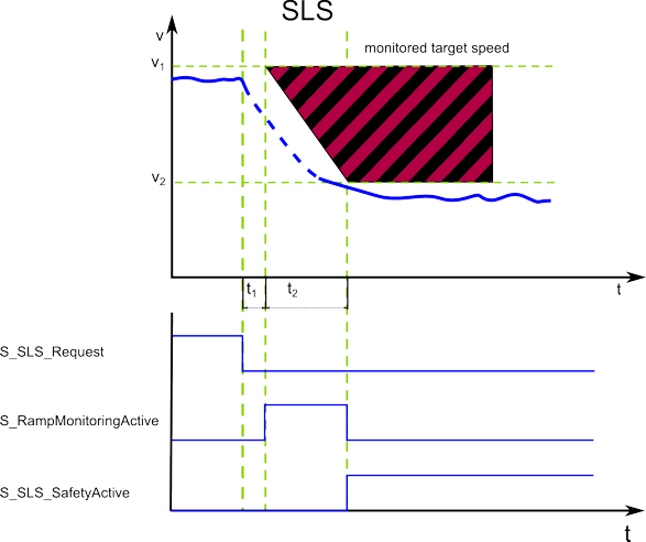
Within the t1 time interval, the standard (non-safety-related) controller also receives the request from the connected process and initiates the motion control function according to the logic and drive parameterization defined in the standard (non-safety-related) application.
After t1 has elapsed, the deceleration of the drive is executed. The maximum allowed duration t2 of this ramp-down phase is defined by the device parameter SLS*_RampMonitoringTime[t2].
At the end of t2, the defined limited target speed SLS*_Speed[v2] must be achieved. Speed V2 is then monitored as long as SLS remains active.
During t2, the deceleration can be monitored by setting the device parameter SLS*_RampMonitoring = Activated.
If ramp monitoring is deactivated, the deceleration curve is not monitored. Even acceleration is allowed during the t2 interval. The target speed must be achieved before the elapse of t2.
If ramp monitoring is activated, the deceleration curve is monitored and must follow the parameterized ramp (as shown in the figure).
If the SLS targeted speed is successfully achieved, the function block switches S_SLS*_SafetyActive = SAFETRUE (see diagram).
If the SS1 fallback function has been activated due to an error detected as described above, this is indicated by S_SS1_SafetyActive = SAFETRUE.
Fallback function
Which function is activated as fallback depends on whether the ramp monitoring is activated or not.
If ramp monitoring is deactivated, the deceleration curve is not monitored. Even acceleration is allowed during the t2 interval. The target speed must be achieved before the elapse of t2. Otherwise, SS1 is activated as the defined fallback function.
If ramp monitoring is activated, the deceleration curve is monitored and must follow the parameterized ramp (as shown in the figure). Otherwise, STO is activated as the defined fallback function.
Application
The SLS function is used when personnel has to access the zone of operation. With the help of the SLS function, the speed is first reduced and then safety-related speed monitoring is activated in order to prevent accidental exceeding of the parameterized speed limit.
By providing four separate SLS functions, the safety-related function could be, for example, extended in a way that several approaching zones could be defined: the closer a person comes to the zone of operation, the more the speed is reduced.
NOTE:
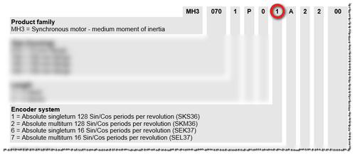
For information on the encoder resolution of the motor used, refer to the SH3/MH3 motor user manual which is part of the EcoStruxure Machine Expert online help (Lexium SH3 Motor - Product Manual or Lexium MH3 Motor - Product Manual).
Determine the resolution as follows:
Digit 10 in the type code of the motor indicates the implemented encoder system.
Section "Type code" in chapter 1 of the motor manual provides information on the number of Sin/Cos periods per revolution.
Motor manual example
Relevant Safety Module device parameters
How to edit the relevant safety-related device parameters: In the EcoStruxure Machine Expert - Safety 'Devices' window, ...
Left-click the Safety Module in the devices tree.
In the Device Parameterization editor on the right, scroll to the relevant parameter section (see table heading below).
Specify the parameters listed in the table below for this safety-related function.
The Safety Module provides four separate SLS functions: SLS1 to SLS4. They can be configured with separate parameters, i.e., each parameter is available for each SLS function. In the following table, * stands as placeholder for SLS1 up to SLS4.
NOTE:
For the most part, the parameters entered here are monitoring parameters. They define the monitoring behavior and thus determine if a safety-related function is executed as defined or if a fallback function is to be executed due to error detection. The actual drive parameterization (such as deceleration parameters, etc.) is defined by you in EcoStruxure Machine Expert. See topic "Functional description".
For detailed information on the value ranges and default values for these parameters, refer to the corresponding chapter for the safety module used in the "Safety Module Parameters and Process Data Items" guide.
|
Parameter section: Safe_Limited_Speed |
|
|
SLS*_StartDelayTime[t1] |
Delay time after which the monitoring of the safety-related function is started. This value must correspond to the time period, the entire motion control system needs to react, i.e., the time after which the standard (non-safety-related) controller is able to initiate the requested safety-related function after receiving the request coded as process data control word via the SERCOS bus. This interval is referred to as t1 in the timing diagram shown above. The value set here must be equal or greater than the entire system response time including the standard system response time. The value must not be smaller than the shortest possible total response time of the involved components, i.e., the earliest point in time, when the drive is able to decelerate. |
|
SLS*_RampMonitoring |
|
|
SLS*_MaxRampVelocity[v1] |
Parameter is only relevant if ramp monitoring is activated (see previous table line). The value influences the gradient of the deceleration ramp (see parameter SLS*_RampMonitoring). |
|
SLS*_RampMonitoringTime[t2] |
The parameter defines the duration in milliseconds after which the target speed (parameter SLS*_Speed[v2]) has to be achieved (t2 in the figure). If ramp monitoring is activated, the value influences the gradient of the deceleration ramp (see parameter SLS*_RampMonitoring). |
|
SLS*_Speed[v2] |
Defines the final target speed which must be achieved at time t2 the latest and then be monitored as long as SLS remains active. The unit value depends on the resolution of the shaft encoder. If ramp monitoring is activated, the value influences the gradient of the deceleration ramp (see parameter SLS*_RampMonitoring). |
NOTE:
When using the SLS function, also the SS1 function must be parameterized.
WARNING
NON-CONFORMANCE TO SAFETY FUNCTION REQUIREMENTS
Verify that the device parameters for the Safety Module correspond to your risk analysis.
Be sure that your risk analysis includes an evaluation for setting incorrectly device parameter values.
Validate the overall safety-related function with regard to the set device parameter values and thoroughly test the application.
Failure to follow these instructions can result in death, serious injury, or equipment damage.
Relevant FB inputs/outputs and bits in status word
Function monitoring request via FB inputs S_SLS_1_Request = SAFEFALSE to S_SLS_4_Request = SAFEFALSE
Function status indication via FB outputs S_SLS_1_SafetyActive to S_SLS_4_SafetyActive (SAFETRUE = safety-related function activated)
In the DWORD output at AxisStatus
bit 9: SLS1 (TRUE = safety-related function activated)
bit 10: SLS2 (TRUE = safety-related function activated)
bit 11: SLS3 (TRUE = safety-related function activated)
bit 12: SLS4 (TRUE = safety-related function activated)