|
Type: |
Function block |
|
Available as of: |
V1.0.0.0 |
|
Inherits from: |
- |
|
Implements: |
- |
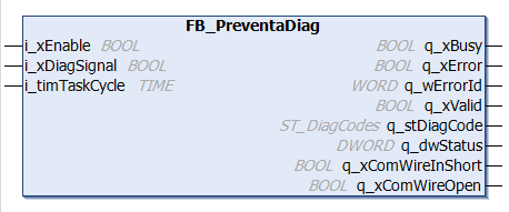
The FB_PreventaDiag function block decodes the bit sequence applied to its input i_xDiagSignal. This sequence is delivered from a Preventa XPS safety module via the auxiliary module output Z1. The pulsed message encodes diagnostic information on the module (see table in section Status Output at q_dwStatus for a list of defined codes).
In order to analyze the incoming sequence and deliver a diagnostic code, the function block needs to be activated by setting its i_xEnable input to TRUE. If the i_xEnable input is reset to FALSE, the sequence analysis is stopped and the function block outputs are set to their default values.
At the i_timTaskCycle input, the cycle time of the task in which the function block is called has to be specified. Using this time value, the function block evaluates whether the task is fast enough to correctly detect the bit sequence signal output by the Preventa XPS safety module. See chapter General Considerations for details.
NOTE: The function block must only be used in a cyclic task and it has to be executed in each task cycle.
The function block implements an internal routine which verifies that it is called in each task cycle. If not, the function block enters the error state (error code 16#1000).
The diagnostic data decoded from the incoming bit sequence is delivered as a STRUCT data type at q_stDiagCode. Depending on the analysis result, the corresponding structure element q_stDiagCodes is set to TRUE. The output q_dwStatus shows the 6-bit code part (without the 4-bit start part) of the last detected bit sequence as a double word.
After detecting a static TRUE signal at input i_xDiagSignal, the output q_xComWireInShort switches to TRUE, thus indicating a possible short circuit in the Preventa XPS safety module. A static FALSE signal at i_xDiagSignal results in switching q_xComWireOpen to TRUE.
The function block provides several outputs for the function block status (q_xBusy, q_xValid) as well as error indications (q_xError and q_wErrorId).
|
Input |
Data type |
Description |
|---|---|---|
|
i_xEnable |
BOOL |
TRUE activates the function block. While activated, the bit sequence at input i_xDiagSignal is continuously read and evaluated. |
|
i_xDiagSignal |
BOOL |
Input for connecting the bit sequence output by the Preventa XPS safety module. Connect this input to the variable which is assigned to the auxiliary output Z1 signal. |
|
i_timTaskCycle |
TIME |
Currently configured cycle time in [ms] of the cyclic task in which the function block is executed. NOTE: To detect the bit sequence correctly, the task cycle time must be equal to or less than 50 ms. See chapter General Considerations for details. |
|
Output |
Data type |
Description |
|---|---|---|
|
q_xBusy |
BOOL |
If this output is set to TRUE, the function block execution is in progress. |
|
q_xError |
BOOL |
If this output is set to TRUE, the function block has detected an error. For details, refer to q_wErrorId. |
|
q_wErrorId |
WORD |
Provides diagnostic and status information as a numeric value. Possible error codes are listed in section Error Codes. |
|
q_xValid |
BOOL |
The output value TRUE indicates for one cycle a valid bit sequence at the i_xDiagSignal input. |
|
q_stDiagCode |
ST_DiagCode |
Diagnostic information decoded from the input bit sequence: the corresponding bit values in the ST_DiagCodes structure are set to TRUE. |
|
q_dwStatus |
DWORD |
Indicates the 6-bit code part (without the 4-bit start part) of the last detected bit sequence converted to a double word data type. Refer to the section below this table. |
|
q_xComWireInShort |
BOOL |
The output value TRUE indicates a static TRUE signal at input i_xDiagSignal. This may indicate a short circuit in the Preventa XPS safety module or the wire from the auxiliary Z1 output to the controller input. |
|
q_xComWireOpen |
BOOL |
The output value TRUE indicates a static FALSE signal input i_xDiagSignal. This may indicate that either the auxiliary output Z1 of the Preventa XPS safety module is not connected correctly to the controller input or the Preventa XPS safety module is switched off. Verify that the wiring and the power supply of the Preventa XPS safety module are correct and the auxiliary Z1 output is not overloaded. |
The sequence is composed of 10 bits with a duration of 200 ms each. The first 4 bits (always 0010) represent the start sequence followed by a 6-bit code sequence.
The following table lists the 6-bit code part of the diagnostic codes sent by the Preventa XPS safety module, as applied to the q_dwStatus output.
|
Code |
Code part of bit sequence |
Decimal value |
Description |
Class. (1) |
|---|---|---|---|---|
|
40 |
101111 |
47 |
Device in operating state Run, safety-related outputs activated. |
S |
|
39 |
101110 |
46 |
Start input activated. Waiting for falling edge for monitored start. |
S |
|
38 |
101010 |
42 |
Waiting for rising edge for automatic/manual or monitored start. |
S |
|
37 |
101011 |
43 |
Waiting for start-up test. |
S |
|
36 |
101001 |
41 |
Input S63 is expected to change its state. |
S |
|
35 |
101000 |
40 |
Input S62 is expected to change its state. In the case of a configuration with antivalent inputs, the inputs S62 and S63 are expected to change their state. |
S |
|
34 |
111000 |
56 |
Input S53 is expected to change its state. |
S |
|
33 |
111001 |
57 |
Input S52 is expected to change its state. In the case of a configuration with antivalent inputs, the inputs S52 and S53 are expected to change their state. |
S |
|
32 |
111011 |
59 |
Input S43 is expected to change its state. |
S |
|
31 |
111010 |
58 |
Input S42 is expected to change its state. In the case of a configuration with antivalent inputs, the inputs S42 and S43 are expected to change their state. |
S |
|
30 |
111110 |
62 |
Input S33 is expected to change its state. |
S |
|
29 |
111111 |
63 |
Input S32 is expected to change its state. In the case of a configuration with antivalent inputs, the inputs S32 and S33 are expected to change their state. |
S |
|
28 |
111101 |
61 |
Input S23 is expected to change its state. |
S |
|
27 |
111100 |
60 |
Input S22 is expected to change its state. In the case of a configuration with antivalent inputs, the inputs S22 and S23 are expected to change their state. |
S |
|
26 |
110100 |
52 |
Input S13 is expected to change its state. |
S |
|
25 |
110101 |
53 |
Input S12 is expected to change its state. In the case of a configuration with antivalent inputs, the inputs S12 and S13 are expected to change their state. |
S |
|
24 |
110111 |
55 |
Safety-related inputs deactivated, safety-related outputs deactivated. |
S |
|
23 |
110110 |
54 |
Instantaneous safety-related outputs are deactivated, delayed safety-related outputs are still activated. |
S |
|
22 |
100111 |
39 |
Synchronization alert. Both synchronized safety-related inputs have been activated, but not within the synchronization time. |
A |
|
21 |
110011 |
51 |
Synchronization alert. One of the synchronized safety-related inputs is still deactivated, but the synchronization time has already elapsed. |
A |
|
20 |
100000 |
32 |
Antivalence alert at input S2x. |
A |
|
19 |
100110 |
38 |
Antivalence alert at input S1x. |
A |
|
18 |
100011 |
35 |
Cross-circuit detected at input used for Cancel Delay function. |
E |
|
17 |
110000 |
48 |
Cross-circuit detected at start input. |
E |
|
16 |
011100 |
28 |
Cross-circuit detected at input S63. |
E |
|
15 |
011101 |
29 |
Cross-circuit detected at input S62. |
E |
|
14 |
011111 |
31 |
Cross-circuit detected at input S53. |
E |
|
13 |
011110 |
30 |
Cross-circuit detected at input S52. |
E |
|
12 |
011010 |
26 |
Cross-circuit detected at input S43. |
E |
|
11 |
011011 |
27 |
Cross-circuit detected at input S42. |
E |
|
10 |
101100 |
44 |
Cross-circuit detected at input S33. |
E |
|
9 |
011000 |
24 |
Cross-circuit detected at input S32. |
E |
|
8 |
001110 |
14 |
Cross-circuit detected at input S23. |
E |
|
7 |
001111 |
15 |
Cross-circuit detected at input S22. |
E |
|
6 |
001101 |
13 |
Cross-circuit detected at input S13. |
E |
|
5 |
001100 |
12 |
Cross-circuit detected at input S12. |
E |
|
4 |
000111 |
7 |
Configuration error detected. |
E |
|
3 |
000110 |
6 |
General error detected in expansion module. |
E |
|
2 |
000011 |
3 |
General error detected. |
E |
|
1 |
101101 |
45 |
Supply voltage is out of tolerance. |
E |
(1) Classification of the message: A = alert, E = error, S = status
If the function block detects an error, the output q_xError switches to TRUE and an error code is indicated at q_wErrorId. This error ID provides detailed information on the error cause.
|
Error ID |
Description |
|---|---|
|
16#1000 |
Function block is not called cyclically. Remedy: Call the function block in a cyclic task and make sure that the function block call cannot be skipped (for example, by a preceding conditional jump). |
|
16#1001 |
Invalid task cycle time connected to input i_timTaskCycle. Remedy: Connect a time value which is equal to or less than 50 ms. See chapter General Considerations for details. |
|
16#1002 |
Synchronization with the bit sequence output by the Preventa XPS safety module not successful. (Error in state 20.) Remedy: Ensure that a valid signal (output at the auxiliary Z1 output of the Preventa XPS safety module) is connected correctly to the function block input and verify that the Preventa XPS safety module is in operating mode. |
|
16#1004 |
The maximum number of invalid bit sequences is exceeded. (Error in state 30.) Remedy: Ensure that a valid signal (output at the auxiliary Z1 output of the Preventa XPS safety module) is connected correctly to the function block input and verify that the Preventa XPS safety module is in operating mode. |
|
16#1005 |
Internal function block error. Remedy: Disable and then re-enable the function block. |