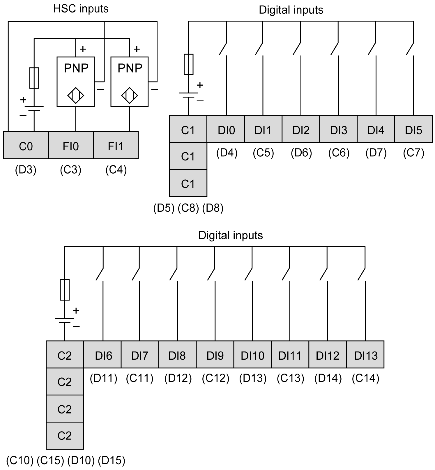
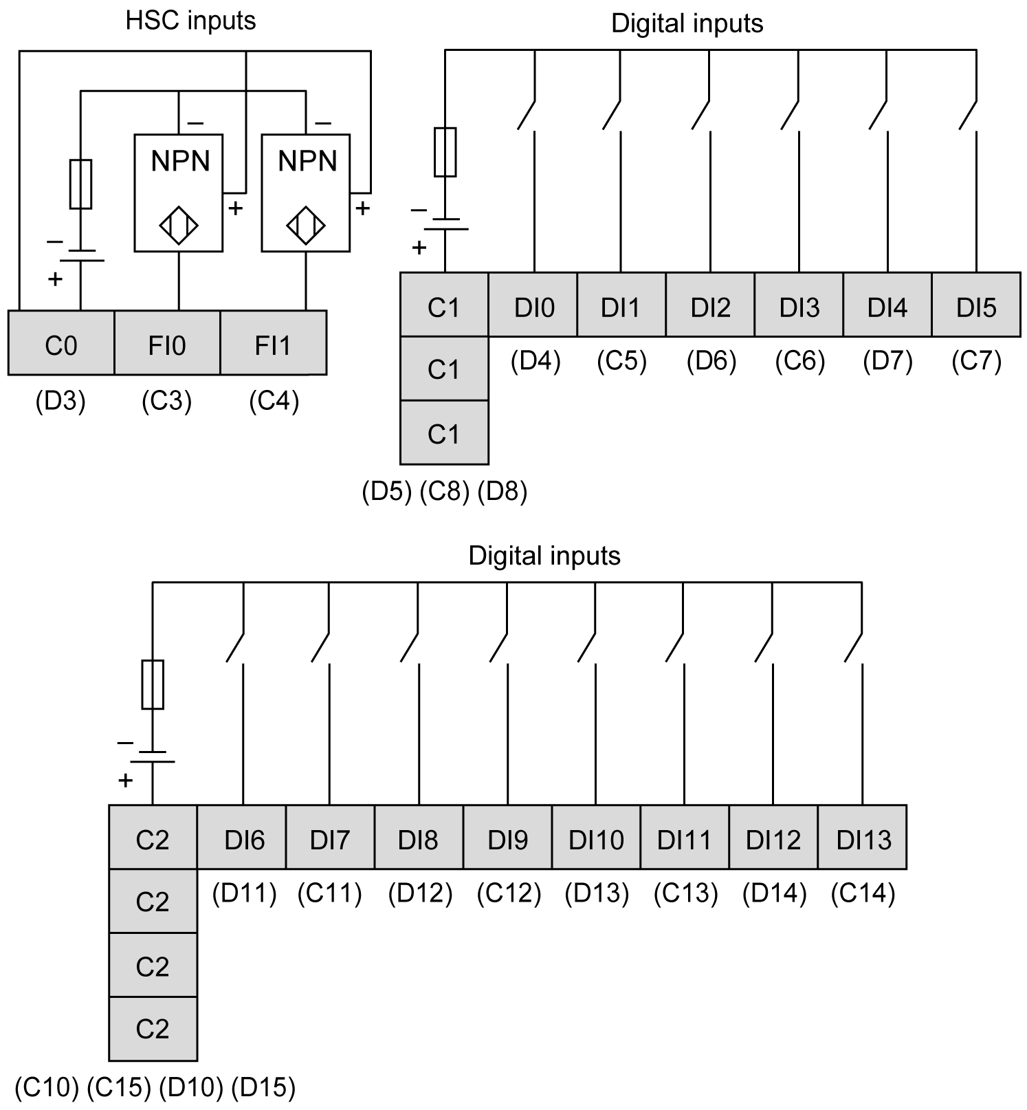
The rear module is equipped with 16 digital inputs.
|
|
|
FIRE HAZARD |
|
Use only the correct wire sizes for the current capacity of the power supplies. |
|
Failure to follow these instructions will result in death or serious injury. |
Input Management Functions Availability
The table describes the possible usage of the rear module inputs:
|
Function |
Input Function |
HSC/PTO/PWM Function |
||||||
|---|---|---|---|---|---|---|---|---|
|
None |
Run/Stop |
Latch |
Event |
HSC |
PTO |
PWM |
||
|
Filter Type |
Integrator |
Integrator |
Bounce |
Bounce |
||||
|
Fast Input1 |
FI0 |
X |
X |
X |
X |
A |
– |
– |
|
FI1 |
X |
X |
X |
X |
B/EN |
– |
– |
|
|
Regular Input |
DI0 |
X |
X |
– |
– |
SYNC |
– |
– |
|
DI1 |
X |
X |
– |
– |
CAP |
– |
– |
|
|
DI2 |
X |
X |
– |
– |
– |
AUX - Drive Ready |
EN |
|
|
DI3 |
X |
X |
– |
– |
– |
– |
SYNC |
|
|
DI4 |
X |
X |
– |
– |
– |
– |
EN |
|
|
DI5 |
X |
X |
– |
– |
– |
– |
SYNC |
|
|
DI6 |
X |
X |
– |
– |
– |
– |
– |
|
|
DI7 |
X |
X |
– |
– |
– |
– |
– |
|
|
DI8 |
X |
X |
– |
– |
– |
– |
– |
|
|
DI9 |
X |
X |
– |
– |
– |
– |
– |
|
|
DI10 |
X |
X |
– |
– |
– |
– |
– |
|
|
DI11 |
X |
X |
– |
– |
– |
– |
– |
|
|
DI12 |
X |
X |
– |
– |
– |
– |
– |
|
|
DI13 |
X |
X |
– |
– |
– |
– |
– |
|
|
X Yes – No 1 Can also be used as a regular input |
||||||||
NOTE: You can use filters and functions to manage the HMI controller inputs.
The figure describes the wiring diagram of the HMISCU6A5, HMISCU8A5, and HMISAC digital input sink type (positive logical):

NOTE: The digital inputs are sink type (positive logical).
The figure describes the wiring diagram of the HMISCU6A5, HMISCU8A5, and HMISAC digital input source type (negative logical):

NOTE: The digital inputs are source type (negative logical).
|
|
|
UNINTENDED EQUIPMENT OPERATION |
|
Do not connect wires to unused terminals and/or terminals indicated as “No Connection (N.C.)”. |
|
Failure to follow these instructions can result in death, serious injury, or equipment damage. |
|
|
|
UNINTENDED EQUIPMENT OPERATION |
|
Use the sensor and actuator power supply only for supplying power to sensors or actuators connected to the module. |
|
Failure to follow these instructions can result in death, serious injury, or equipment damage. |