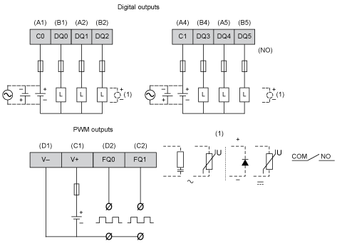
The rear module is equipped with 6 relay outputs and 2 transistor outputs that you can manage.
|
|
|
FIRE HAZARD |
|
Use only the correct wire sizes for the current capacity of the power supplies. |
|
Failure to follow these instructions will result in death or serious injury. |
Output Management Functions Availability
The table describes the possible usage of the rear module outputs:
|
Function |
Output Function |
|||
|---|---|---|---|---|
|
None/Run/Stop |
Latch/Event |
PWM/PTO/HSC |
||
|
Filter Type |
Integrator |
Bounce |
||
|
Fast Output1 |
FQ0 |
X |
X |
X |
|
FQ1 |
X |
X |
X |
|
|
Digital Output |
DQ0 |
X |
– |
– |
|
DQ1 |
X |
– |
– |
|
|
DQ2 |
X |
– |
– |
|
|
DQ3 |
X |
– |
– |
|
|
DQ4 |
X |
– |
– |
|
|
DQ5 |
X |
– |
– |
|
|
X Yes – No 1 Can also be used as a regular output |
||||
For additional information about fast output protection, refer to Protecting Outputs from Inductive Load Damage.
|
|
|
UNINTENDED EQUIPMENT OPERATION |
|
Wire the outputs correctly according to the wiring diagram. |
|
Failure to follow these instructions can result in death, serious injury, or equipment damage. |
The figure describes the wiring diagram of the HMISCU6B5, HMISCU8B5 and HMISBC digital outputs:

To improve the life time of the contacts, and to protect from potential damage by reverse EMF when using inductive load, connect:
oa free wheeling diode in parallel to each inductive DC load
oan RC snubber in parallel of each inductive AC load
|
|
|
UNINTENDED EQUIPMENT OPERATION |
|
Do not connect wires to unused terminals and/or terminals indicated as “No Connection (N.C.)”. |
|
Failure to follow these instructions can result in death, serious injury, or equipment damage. |