The embedded I/O function allows configuring of the controller inputs.
The table describes the digital inputs of the controllers:
|
Reference |
Digital Input |
Digital Output |
|---|---|---|
|
HMISCU6A5 |
14 regular inputs and 2 fast inputs (HSC) |
8 regular outputs and 2 fast outputs (PTO)(1) |
|
HMISCU8A5 |
||
|
HMISAC |
||
|
HMISCU6B5 |
6 regular inputs and 2 fast inputs (HSC) |
6 regular outputs and 2 fast outputs (PTO)(1) |
|
HMISCU8B5 |
||
|
HMI SBC |
||
|
1 The fast outputs can be used either as regular outputs or as fast outputs for Pulse Train Output (PTO), Pulse Width Modulation (PWM) functions, or reflex output for high speed counter (HSC). |
||
Accessing the I/O Configuration Window
|
Step |
Description |
|---|---|
|
1 |
Click HMISCUxx5 > Embedded Functions > IO in the Devices tree. |
|
2 |
Click the I/O Configuration tab. |
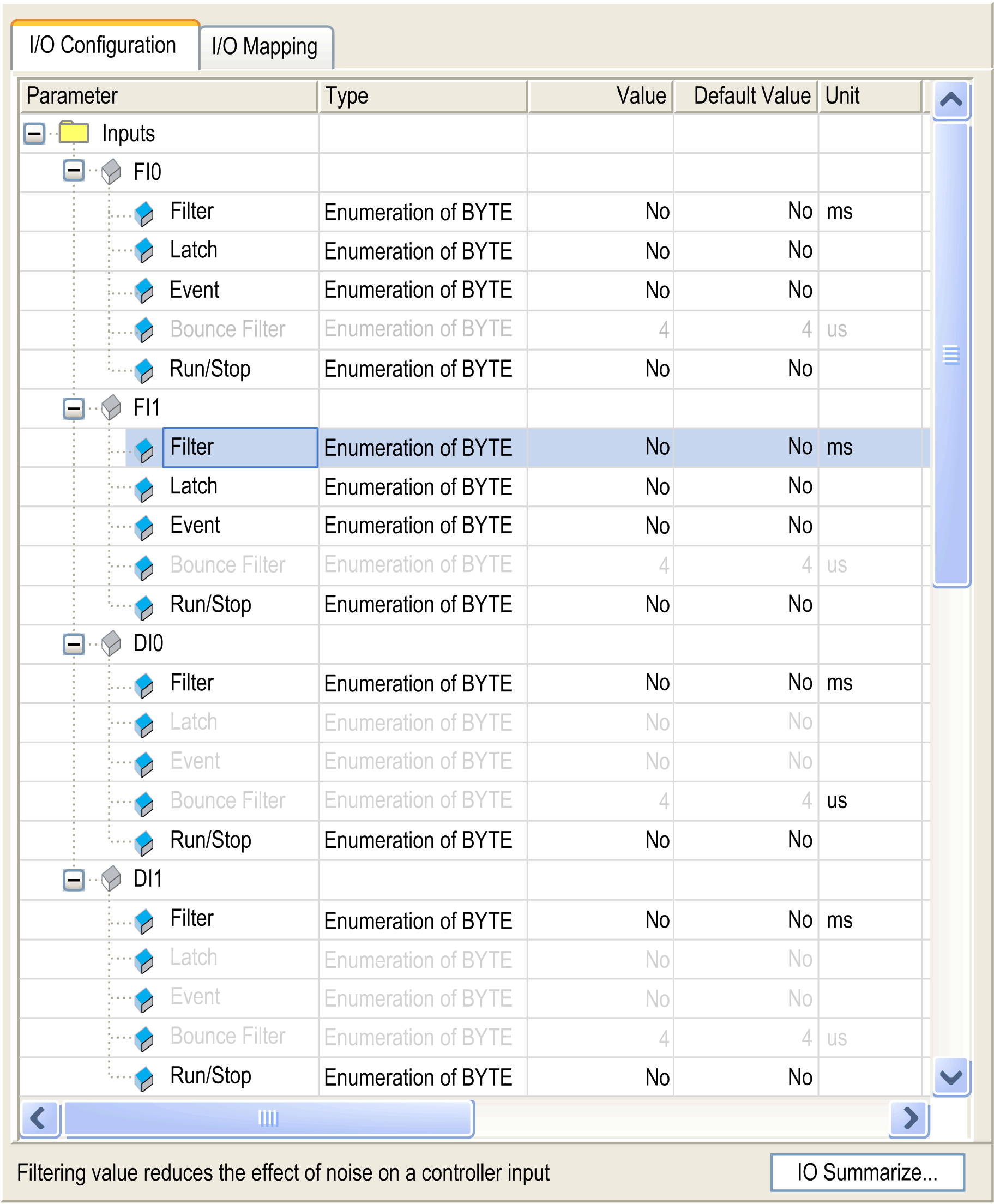
The window allows you to configure the embedded digital inputs:

NOTE: If the selection is gray, the parameter is unavailable.
NOTE: For more information on the I/O Mapping tab, refer to the CoDeSys online help in SoMachine.
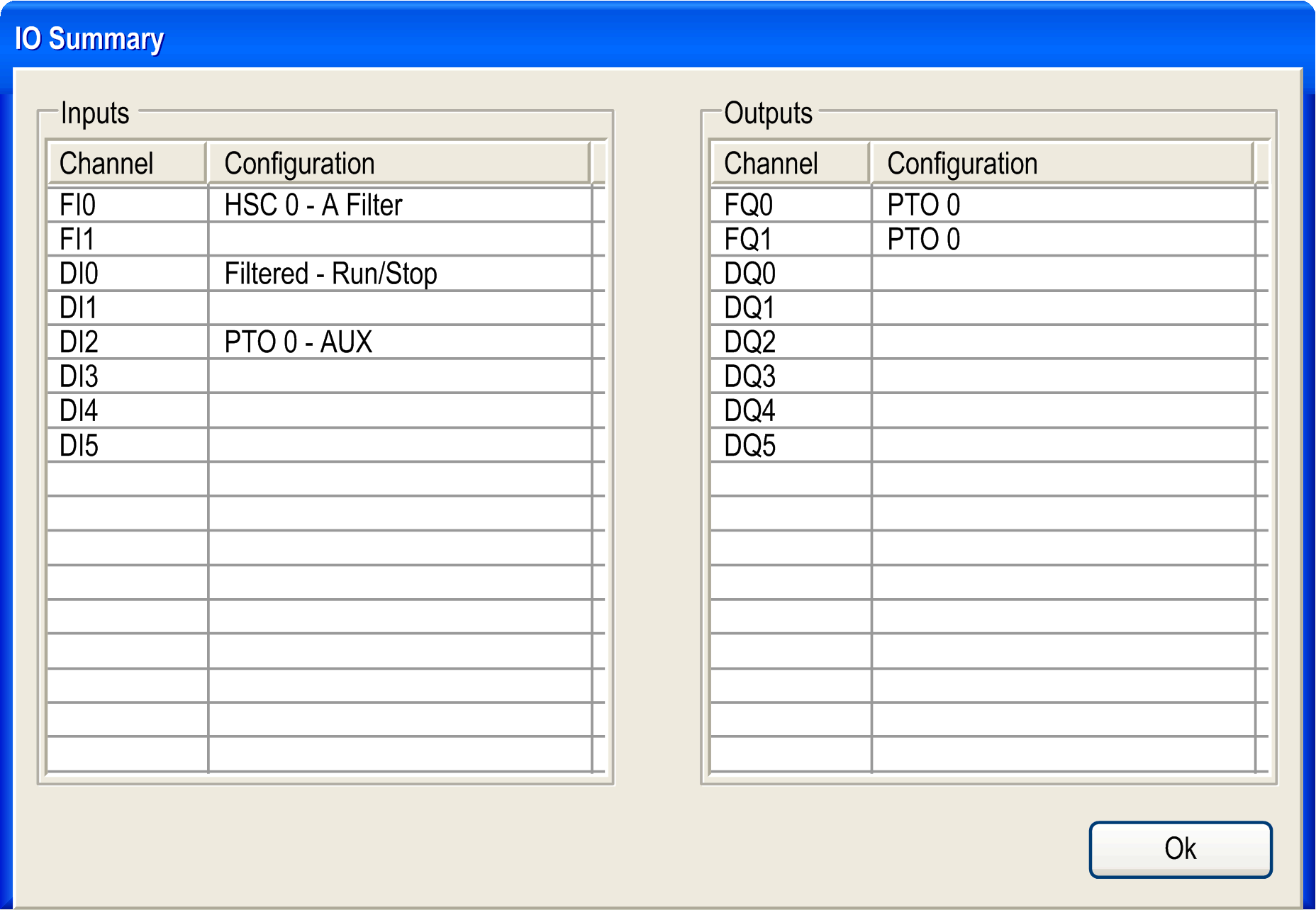
When you click the IO Summarize button, the IO Summary window appears. It allows you to check your configured I/O mapping:

For each digital input, you can configure the parameters:
|
Parameter |
Value |
Description |
Constraint |
|---|---|---|---|
|
Filter |
No* 3 ms 12 ms |
Reduces the effect of noise on a controller input. |
Available if Latch and Event are disabled. In the other cases, this parameter is disabled and its value is No. |
|
Latch |
No* Yes |
Allows incoming pulses with amplitude widths shorter than the controller scan time to be captured and recorded. |
This parameter is only available for fast inputs FI0 and FI1. Available if Run/Stop is disabled. |
|
Event |
No* Rising edge Falling edge Both edges |
Event Detection for the purpose of triggering an External Task. |
This parameter is only available for fast inputs FI0 and FI1. Available if both Latch and Run/Stop are disabled. |
|
Bounce Filter |
4 µs* 40 µs |
Reduces the effect of bounce on a controller input. |
Available if Latch is enabled or Event is enabled. In the other cases, this parameter is disabled and its value is 4 µs. |
|
Run/Stop |
No* Yes |
The Run/Stop input can be used to run or stop a program in the controller. |
Any input can be configured as Run/Stop, but only one input can be configured for this purpose. |
|
* parameter default value |
|||
NOTE: The parameter is unavailable if the selection displays as gray in color.
This table presents the different states:
|
Input states |
Result |
|---|---|
|
State 0 |
Stops the controller and ignores external Run commands. |
|
A rising edge |
From the STOPPED state, initiate a start-up of an application in RUNNING state. |
|
State 1 |
The application can be controlled by: oSoMachine (Run/Stop) oapplication (Controller command) onetwork command (Run/Stop command) |
NOTE: Run/Stop input is managed even if the option Update I/O while in stop is not selected in Controller Device Editor (PLC settings tab).
Inputs assigned to configured expert functions cannot be configured as Run/Stop inputs.
For further details about controller states and states transitions, refer to Controller State Diagram.
|
|
|
UNINTENDED MACHINE OR PROCESS START-UP |
|
oVerify the state of security of your machine or process environment before applying power to the Run/Stop input. oUse the Run/Stop input to help prevent the unintentional start-up from a remote location. |
|
Failure to follow these instructions can result in death, serious injury, or equipment damage. |