1 PTO can be configured on the controller.
A configured PTO uses 2 fast / pulse outputs for pulse and direction and 1 digital input (an optionally configured auxiliary).
|
Step |
Action |
|---|---|
|
1 |
In the Devices tree, double-click HMISCUxx5 > Embedded Functions > PTO_PWM. Result: The PTO_PWM window is displayed. |
|
2 |
Select PTO in the PTO0• > Mode drop down menu. |
|
3 |
An instance of the PTO is created, it can be renamed in the Variable field. Default name is: PTO00. |
Configuration Window Description
This table describes each parameter available when the embedded PTO_PWM is configured in PTO mode:
|
Parameter |
Value |
Default Value |
Unit |
Description |
|
|---|---|---|---|---|---|
|
Mode |
Not Used PTO PWM |
Not Used |
– |
The mode selected is PTO. |
|
|
Pulse/Direction Direction/Pulse |
Pulse/Direction |
– |
Mode of generation of outputs |
||
|
Acc./Dec. Unit |
ms Hz/ms |
ms |
– |
Acceleration/Deceleration Unit NOTE: When this setting is changed between ms and Hz/ms, the values for Acc. max., Dec. max., and Dec. Fast Stop will be automatically converted in the user interface. |
|
|
Acc. max. |
1...49999 |
20 |
ms |
Acceleration time minimum value when Acc./Dec. Unit is set to ms. |
|
|
1...50000 |
2500 |
Hz/ms |
Acceleration rate maximum value when Acc./Dec. Unit is set to Hz/ms. |
||
|
Dec. max. |
1...49999 |
20 |
ms |
Deceleration time minimum value when Acc./Dec. Unit is set to ms. |
|
|
1...50000 |
2500 |
Hz/ms |
Deceleration rate maximum value when Acc./Dec. Unit is set to Hz/ms. |
||
|
Dec. Fast Stop |
1...49999 |
100 |
ms |
When the Acc./Dec. Unit is set to ms, the deceleration rate used in a Dec. Fast Stop (triggered by a Drive Ready input low, limits exceeded, detected errors) is calculated from this time value: Dec. Fast Stop rate = Maximum Frequency (Hz) / Dec. Fast Stop time (ms). oTherefore, the actual Fast Stop Deceleration time = current frequency / calculated Deceleration Fast Stop rate. o If the newly calculated deceleration rate is less than 1 Hz/ms, the rate used will be just 1 Hz/ms. NOTE: If the Stop Frequency is configured to be 0 Hz, the frequency of the last pulse period = SQRT ((deceleration rate in Hz/s) / 2) rounded to the nearest whole number. Refer to Appendix for more information. |
|
|
1...50000 |
500 |
Hz/ms |
|||
|
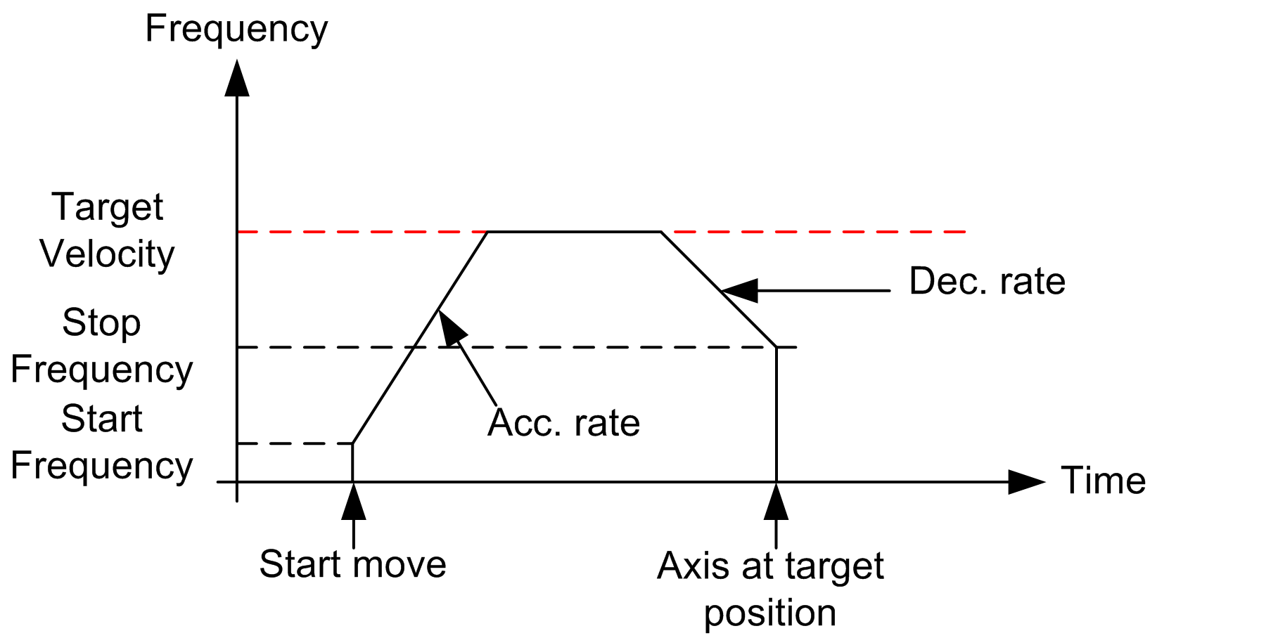
Start |
0...50000 |
0 |
Hz |
On execution of PTOMoveRelative, the first pulse period during acceleration starts at this frequency. NOTE: If the Start Frequency is set to 0 Hz, the actual start frequency = SQRT ((acceleration rate in Hz/s) / 2) rounded to the nearest integer. Refer to Appendix for more information |
|
|
Stop |
0...50000 |
0 |
Hz |
On execution of PTOMoveRelative, PTOStop, Dec. Fast Stop, the last pulse period during deceleration ends at this frequency. NOTE: If the Stop Frequency is set to 0 Hz, the actual stop frequency = SQRT ((deceleration rate in Hz/s) / 2) rounded to the nearest integer. Refer to Appendix for more information |
|
|
Maximum |
1...50000 |
50000 |
Hz |
Maximum frequency allowed by PTOMoveRelative function block during operation. Frequencies higher than this value if set in a motion function block will return an error. |
|
|
AUX |
Not used Drive Ready |
Not used |
– |
Specific input dedicated to the Drive Ready information. NOTE: reference point detection (origin) is not supported on HMI SCU. |
|
|
AUX Filter |
3 12 |
3 |
ms |
Filtering value reduces the effect of bounce on the auxiliary input |
|
This example shows an actual fast stop deceleration time using the following settings:
|
Parameter |
Value |
Units |
|---|---|---|
|
Dec. Fast Stop |
10,000 |
ms |
|
Maximum Frequency |
50,000 |
Hz |
When the current frequency of a running motion command is at 10,000 Hz, and an error triggers a Fast Stop (for example, triggering another PTOMoveRelative while a motion is already in progress):
oDec. Fast Stop rate = Maximum Frequency / Dec. Fast Stop time = 50,000 Hz / 10,000 ms = 5 Hz/ ms
oSince the current frequency is 10,000 Hz, actual Dec. Fast Stop time = current frequency / Dec. Fast Stop rate = 10,000 Hz / 5 Hz/m = 2000 ms
|
Step |
Action |
|---|---|
|
1 |
Enable the PTO channel by selecting PTO in the PTO0• > Mode drop down menu. |
|
2 |
Select the mode of generation of outputs in the PTO0• > Output Mode drop down menu. |
|
3 |
Configure the Acc./Dec. Unit, Acc.max, Dec. max, and Dec. Fast stop parameters. |
|
4 |
Configure the Frequency parameters: Start, Stop, and Maximum. |
|
5 |
Optionally enable the AUX input. |
|
6 |
Configure the PTO0• > AUX input filtering value (if enabled at step 5). |
The configuration defined can be viewed as a configuration profile:
