FUNCTION_BLOCK SMC_ToolCorr
This function block is replaced by SMC_ToolRadiusCorr.
SMC_ToolCorr creates a shifted path. In the shifted path each point has a defined distance to the original point (tool radius correction). A typical application is the milling of a programmed contour with a milling drill of a certain diameter. In order to compensate the radius of the drill, the milling drill must follow anshifted path.

Note
The shifted path may contain self-intersections or loops That would mean that the desired contour would be destroyed during passing the shifted path. (See the example below.) To avoid such intersections, use SMC_AvoidLoop .

Proceeding of SMC_ToolCorr
All SMC_GEOINFO objects found in the Input SMC_OUTQUEUE structure will be checked one after the other. If Bit1 (Bit2) of the variable Intern_Mark is set in one of these objects, then starting from there – in direction of motion - the path will be shifted to the left (right) by the currently set tool radius.
In order to get a continuous path the input eMode have to set on one the desired mode:
TC_RAMP_IN: this mode is used to ramp into the offset path,
which means that the start position stays unchanged, but the end position is offset. All further objects are offset as well until the tool radius correction is switched off by setting Bit0 of Intern_Mark. Then, the start position of the object is still offset, but the end position is the original one.
TC_BLIND_POS: this mode is used for insetting a positioning object
(SMC_GEOINFO.iMoveType = 100), resp. if such a positioning object is already preceding the object. It will be shifted directly to the start point of the shifted path. Each further object will then be offset as well, until Bit0 of Intern_Mark gets set, what will stop the tool radius correction. A further positioning object will be inserted.
SMC_NCDecoder will set these bits in reaction on the instructions G41/G42/G40. In other words: The tool radius correction will be done for all objects located between the instructions G41 and G40 resp. G42 and G40.
Example 1: Simple tool correction
G-Code:
N0 G0 X10 Y-10 F10 E100 E-100
N1 G41 D10
N2 G1 X20 Y-10
N2 G1 X30 Y-10
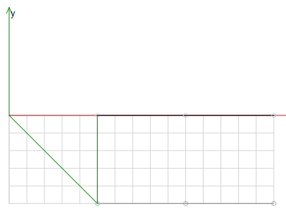
CNC path without tool correction:

CNC path with tool correction, eMode=TC_BLIND_POS:
Example 2: Tool correction with eMode=TC_BLIND_POS
G-Code
N000 G41 D1 (WRK an)
N010 G00 X3 F100 E1000 E-1000
N020 G01 X5 Y10
N030 G01 X7 Y10
N040 G01 X10 Y0
N050 G00 X20
N060 G40 (WRK off)
In the example above the element in sentence N010 ramps in the shifted path. The element in sentence N050 is used for ramping out. The following figure shows the CNC path with tool correction and eMode=TC_BLIND_POS:

It is highly recommended, that the first and last element in the parenthesis is a positioning element (G0). If this is not the case, the first move is to the original starting point of the object, and the next move is to the offset start point.
Example 3: Tool correction with eMode=TC_RAMP_IN
G-Code
% G-code RampIn and Rampout in radius correction
N0 G0 X10.0 Y-15.0 F10.0 E100 E-100.0
N1 G41 D10.0
N2 G1 X20.0 Y-15.0 (RampIn)
N3 G1 X30.0 Y-15
N4 G40
N5 G1 X40.0 Y-15.0 (RampOut)
Condition for RampIn and RampOut is a linear movement (G1 in sentence N1 and sentence N5). The following figure shows the CNC path with radius correction eMode=TC_RAMP_IN:

Example 4: Tool correction with eMode=TC_RAMP_IN
G-Code
N000 G41 D3 (WRK an)
N010 G01 X3 Y10 F100 E1000 E-1000
N020 G01 X7 Y10
N030 G01 X10 Y0
N040 G40 (WRK off)
N050 G01 X20
In the example above the element in sentence N010 ramps in the shifted path. The element in sentence N050 is used for ramping out.

Note the first element inside the G41/G40 parenthesis is used for ramping in and the next is used for ramping out and must be a line (G01).
Example 5: Milling a contour with a milling drill moved in Z-direction
G-Code
(First section)
N000 G41 D1 (WRK on) F100 E1000 E-1000
N010 G00 X3
N020 G01 Z10
N030 G01 X5 Y10 (Beginning of the milling contour)
N040 G01 X7 Y10
N050 G01 X10 Y0 (End of the milling contour)
N060 G01 Z0
N070 G40 (WRK off)
N080 G00 X20
(Second section)
N080 G42 D1 (WRK on)
N090 G00 X23
N100 G01 Z10
N110 G01 X25 Y10
N120 G01 X27 Y10
N130 G01 X30 Y0
N140 G01 Z0
N150 G40 (WRK off)
N160 G00 X40
The example above shows the using of the tool radius correction (WRK) together with the cutter positioning in Z-direction. The mode is set to BLIND_POS. The first element in the G41/G42-G40 parenthesis is to be a positioning to the start point of the contour. The next step is the positioning of the shaping tool in Z. Then the contour starts. At last the Z-axis is positioned off the workpiece and the tool radius correction is turned off. The second section of the example shows a tool radius correction in another direction. The following figure shows the milling CNC path along the Z-axis:

InOut:
|
Scope |
Name |
Type |
Initial |
Comment |
|
Input |
bExecute |
BOOL |
Starts on rising edge. |
|
|
bAbort |
BOOL |
If TRUE, the current processing of this function block is aborted |
||
|
bAppend |
BOOL |
As long as this input remains FALSE, the DataOutQueue will be cleared at each reset. As long as it remains TRUE, newly incoming data will be written to the end of the DataOutQueue. |
||
|
poqDataIn |
POINTER TO SMC_OUTQUEUE |
The input path queue. |
||
|
dToolRadius |
LREAL |
This variable contains the value, which – added to the current ToolRadius of the SMC_GEOINFO object – will determine the tool radius by which the path is to be shifted (see above). This value can be modified online. Thus it is possible to predefine the value offline (by the SMC_GEOINFO structure) and to modulate it online. Note that a tool radius correction that gets initiated during a shift of the block will cause the abort of the path correction and therefore should be avoided! But it is possible to do the radius correction during a reset or within a phase guaranteeing that the module is not currently shifting a block (Status = TC_ORIG). Default-Value: 0. |
||
|
nSizeOutQueue |
UDINT |
This variable contains the size of the data buffer, the list of SMC_GEOINFO structure objects will be written to. This buffer must be at least five times as big as a SMC_GEOINFO structure itself. Otherwise, SMC_NCDecoder will not execute any actions at all. Its size may be predefined, but may be modified later only during a reset. It is recommended to create the buffer as described by the example below. ExampleBuf: Array[1..50] of SMC_GeoInfo. The correct buffer size will then be retrieved by use of the operator sizeof(ExampleBuf). |
||
|
pbyBufferOutQueue |
POINTER TO ARRAY [0..0] OF SMC_GEOINFO |
This input must point to the first byte of the memory area that is allocated for the SMC_OUTQUEUE structure. This area must be at least as big as defined in nSizeOutQueue. Typically the allocation of the memory buffer is done in the declaration part of the IEC-program by defining an array of SMC_GEOINFO (for example BUF: ARRAY[1..50] OF SMC_GEOINFO; for a buffer that can store 50 path elements). The value may be predefined, but may be modified later on only during a reset. |
||
|
eMode |
TC_RAMP_IN |
Mode that defines the transition between offset and non- offset path. |
||
|
Output |
bDone |
BOOL |
This variable is be set to TRUE as soon as the input path has been processed completely. The function block does not perform any further actions until it gets a reset. |
|
|
bBusy |
BOOL |
TRUE, while execution of function block is not finished |
||
|
bError |
BOOL |
Signals, that an error has occurred within the function block |
||
|
wErrorID |
SMC_ERROR |
Error identification |
||
|
poqDataOut |
POINTER TO SMC_OUTQUEUE |
This variable points to the SMC_OUTQUEUE structure that manages the decoded SMC_GEOINFO objects. |
||
|
iStatus |
TC_ORIG |
Shows the current status of the module.
|