Parts Identification and Functions
|
Side |
XBT GT1105 |
XBT GT1135/1335 |
|---|---|---|
|
Front |
|
|
|
Rear |
|
|
|
Bottom |
|
|
|
Part |
Description |
|---|---|
|
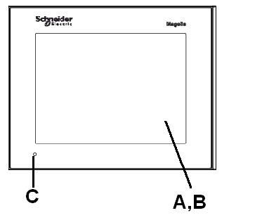
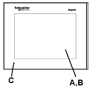
A |
Display: displays user created screens and remote equipment variables. |
|
B |
Touch panel: performs screen change operations and sends data to the host (PLC). |
|
C |
Status LED |
|
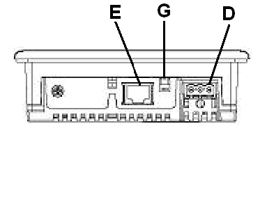
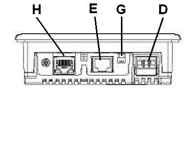
D |
Power input Terminal block: connects the XBT GT power cable’s input and ground wires to the XBT GT. |
|
E |
Serial I/F (host I/F 8 pin RJ-45): connects a RS-232C or RS-485 (serial) cable (from the host/PLC) to the XBT GT (Y port). |
|
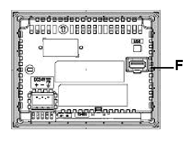
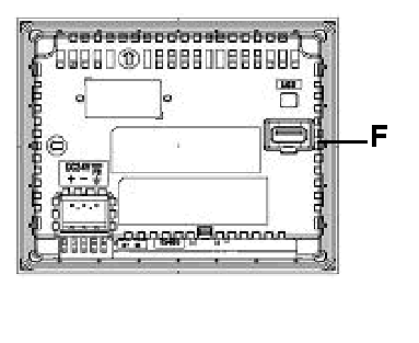
F |
USB interface (USB1.1): connects a data transfer cable or peripherals or PLC USB terminal port to XBT GT. |
|
G |
RS-485 Line Polarization Selector Switch. |
|
H |
Ethernet interface (LAN) (10Base-T/100Base-TX) (except XBT GT1105): RJ-45 connector is used, and the LEDs turn ON or OFF to indicate the current status. oGreen ON: Data transmission available. oGreen Flashing: Data is transmitting. oGreen OFF: No connection or loss of communication. oYellow ON: Connected to 100BASE-TX. oYellow OFF: Connected to 10BASE-T or No connection. |
|
Side |
XBT GT2000 series Part Identification |
|---|---|
|
Front |
|
|
Rear |
|
|
Left and Right |
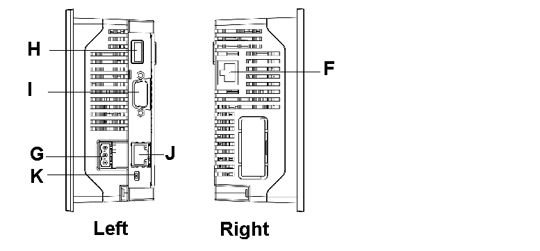
|
|
CF Card Cover Open |

|
|
Part |
Description |
|---|---|
|
A |
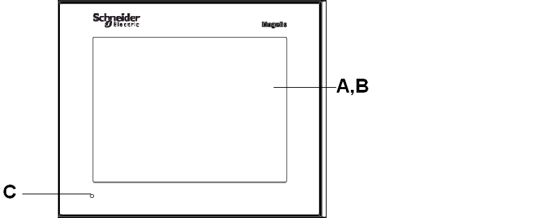
Display: displays user created screens and remote equipment variables. |
|
B |
Touch panel: performs screen change operations and sends data to the host (PLC). |
|
C |
Status LED: oGreen (steady): normal operation (power is ON) or OFFLINE operation. oOrange (steady): backlight burnout is detected. oOrange (blinking): during software startup. oRed (steady): when power is turned ON. oNot lit: power is OFF. |
|
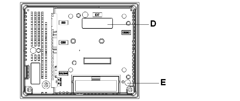
D |
Expansion unit interface: connects expansion units with communication features. |
|
E |
CF card access lamp (except XBT GT2110): oGreen ON: the CF card is inserted and the cover is closed, or the CF card is being accessed. oGreen OFF: the CF card is not inserted or is not being accessed. |
|
F |
Ethernet interface (10Base-T/100Base-TX) (except XBT GT2110/2120): RJ-45 connector is used, and the LED turns ON or OFF to indicate the current status. oGreen ON: data transmission available. oGreen OFF: no connection or subsequent loss of communication. oYellow ON: data transmission is occurring. oYellow OFF: no data transmission. |
|
G |
Power input terminal block: connects the XBT GT power cable’s input and ground wires to the XBT GT. |
|
H |
USB interface (USB1.1): connects a data transfer cable or peripherals or PLC USB terminal port to XBT GT. |
|
I |
Serial interface COM1: connects a RS-232C or RS-422-485 (serial) cable (from the host/PLC) to the XBT GT (COM1 port). |
|
J |
Serial interface COM2: connects a RS-485 (serial) cable (from the PLC) to the XBT GT (COM2 port). |
|
K |
RS-485 line polarization selector switch. |
|
L |
CF card cover: covers the CF card slot. This cover must be closed when accessing the CF card (except XBT GT2110)(See Location of CF Card DIP Switches). |
|
M |
CF card socket: permits insertion of the CF card. |
|
Side |
XBT GT2430 Part Identification |
|---|---|
|
Front |
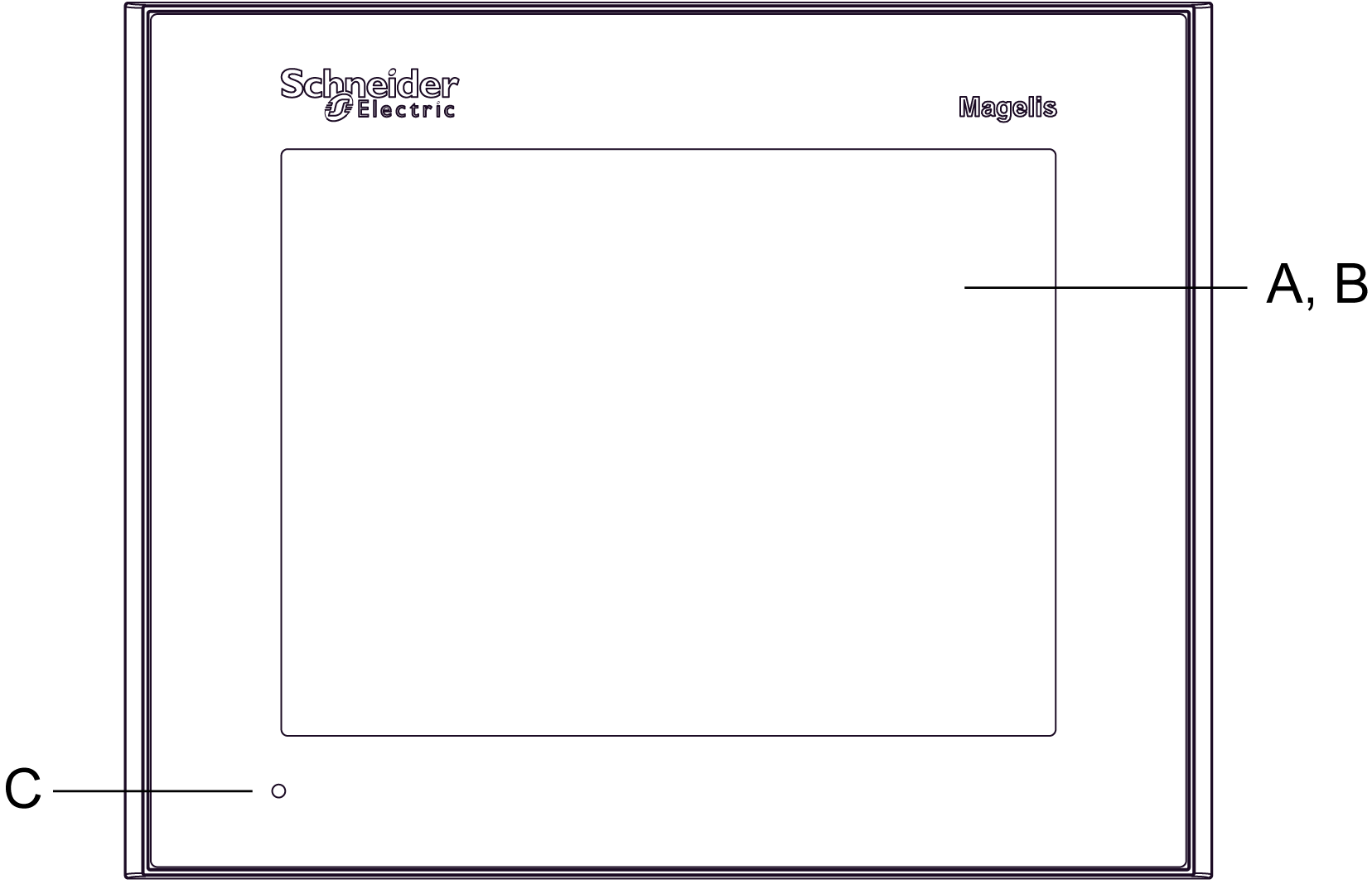
|
|
Rear |
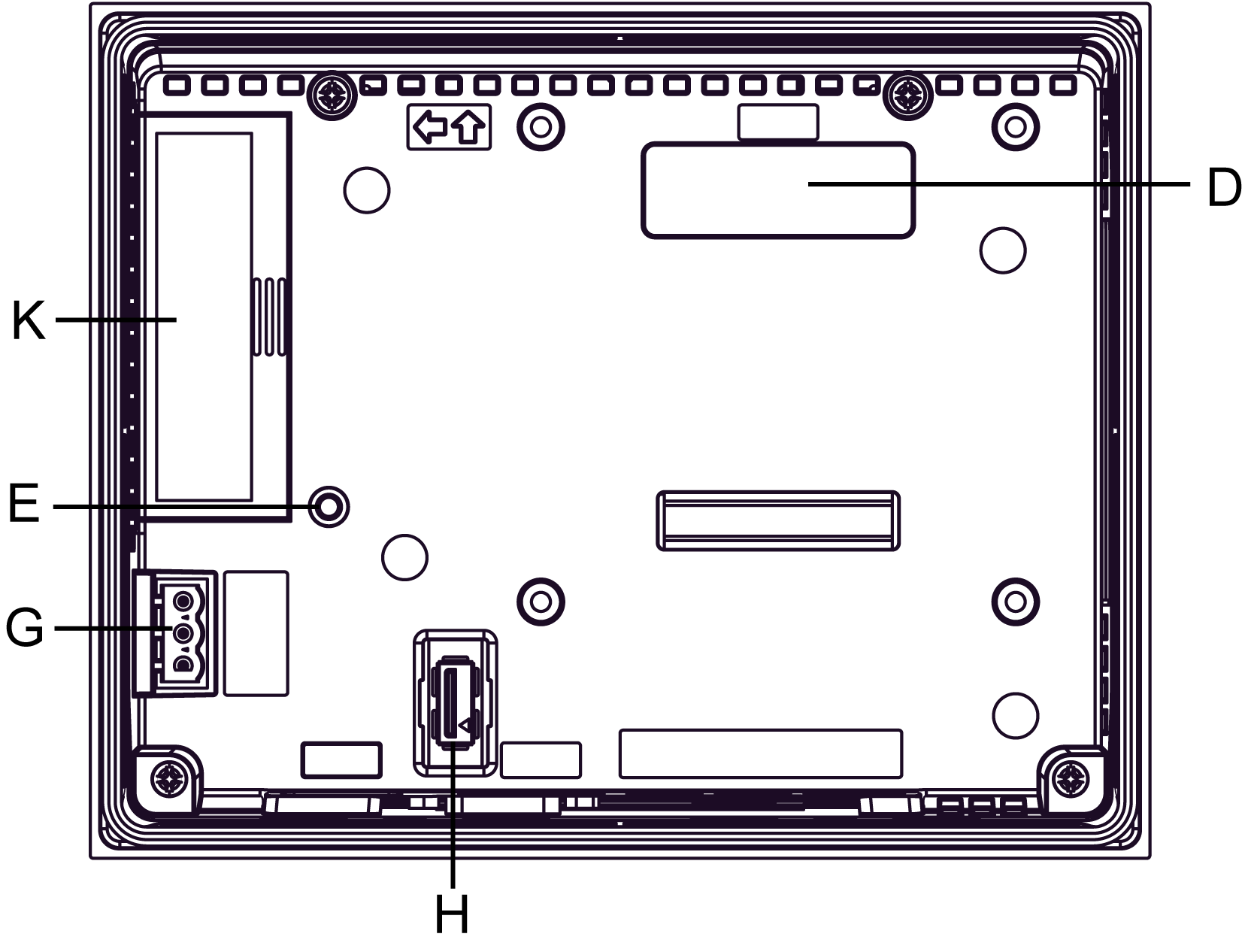
|
|
Bottom |
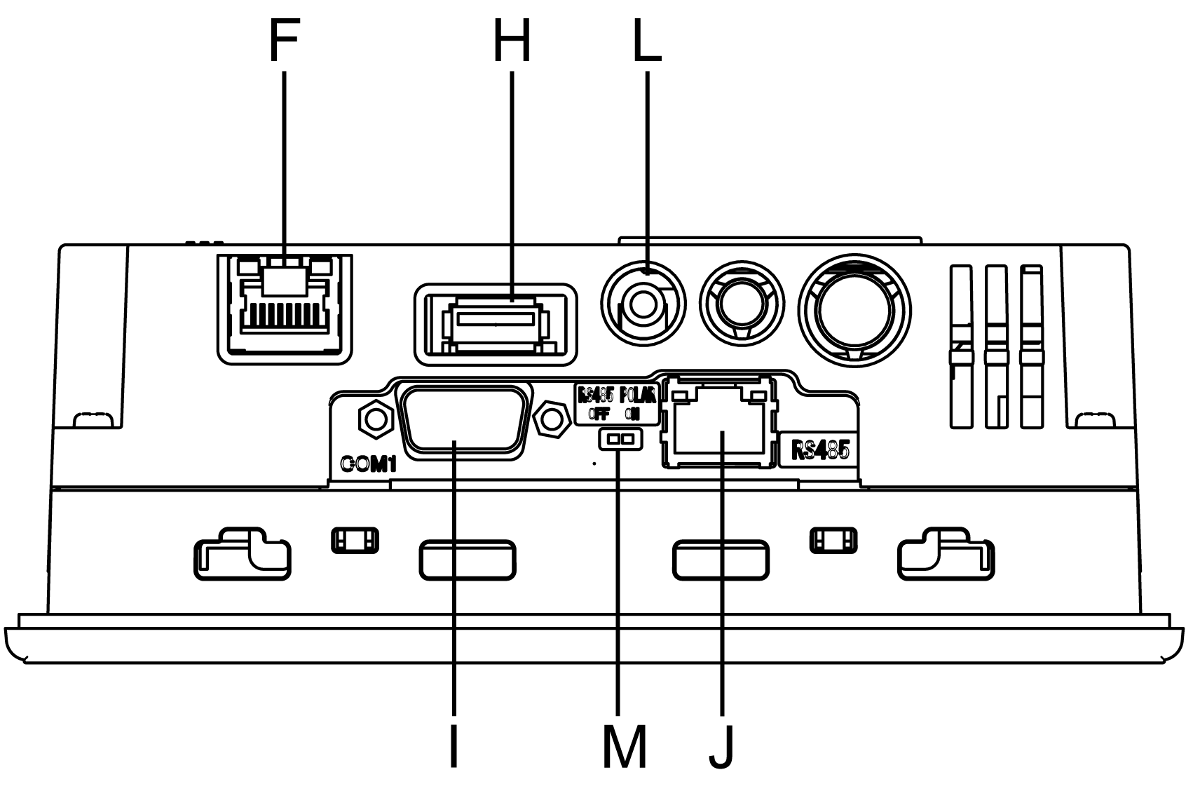
|
|
Part |
Description |
|---|---|
|
A |
Display: displays user created screens and remote equipment variables. |
|
B |
Touch panel: performs screen change operations and sends data to the host (PLC). |
|
C |
Status LED: oGreen (steady): normal operation (power is ON) or OFFLINE operation. oOrange (steady): backlight burnout is detected. oOrange (blinking): during software startup. oRed (steady): when power is turned ON. oNot lit: power is OFF. |
|
D |
Expansion unit interface: connects expansion units with communication features. |
|
E |
CF card access lamp: oGreen ON: the CF card is inserted and the cover is closed, or the CF card is being accessed. oGreen OFF: the CF card is not inserted or is not being accessed. |
|
F |
Ethernet interface (10Base-T/100Base-TX): RJ-45 connector is used, and the LED turns ON or OFF to indicate the current status. oGreen ON: data transmission available. oGreen OFF: no connection or subsequent loss of communication. oYellow ON: data transmission is occurring. oYellow OFF: no data transmission. |
|
G |
Power input terminal block: connects the XBT GT power cable’s input and ground wires to the XBT GT. |
|
H |
USB interface (USB1.1): connects a data transfer cable or peripherals or PLC USB terminal port to XBT GT. |
|
I |
Serial interface COM1: connects a RS-232C or RS-422-485 (serial) cable (from the host/PLC) to the XBT GT (COM1 port). |
|
J |
Serial interface COM2: connects a RS-485 (serial) cable (from the PLC) to the XBT GT (COM2 port). |
|
K |
CF card cover: covers the CF card slot. This cover must be closed when accessing the CF card (See Location of CF Card DIP Switches). |
|
L |
Sound Output Interface. |
|
M |
RS-485 line polarization selector switch. |
|
Side |
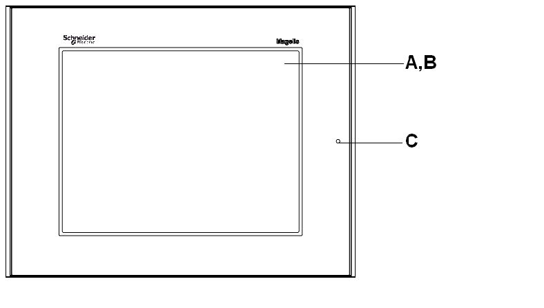
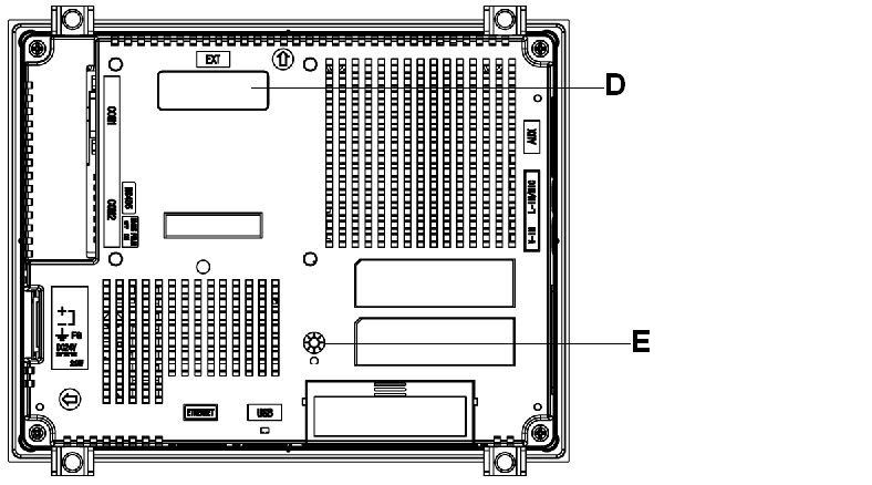
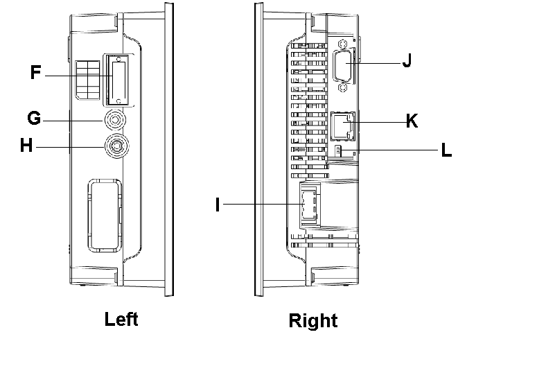
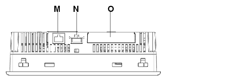
XBT GT4000 series Part Identification |
|---|---|
|
Front |
|
|
Rear |
|
|
Left and Right |
|
|
Bottom |
|
|
Part |
Description |
|---|---|
|
A |
Display: displays user created screens and remote equipment variables. |
|
B |
Touch Panel: performs screen change operations and sends data to the host (PLC). |
|
C |
Status LED: oGreen (steady): normal operation (power is ON) or OFFLINE operation. oOrange (steady): backlight burnout is detected. oOrange (blinking): during software startup. oRed (steady): when power is turned ON. oNot lit: power is OFF. |
|
D |
Expansion unit interface: connects expansion units with communication features. |
|
E |
CF card access lamp: oGreen ON: the CF Card is inserted and the Cover is closed, or the CF Card is being accessed. oGreen OFF: the CF Card is not inserted or is not being accessed. |
|
F |
Auxiliary input/output/voice output interface (AUX). This interface is used for: oExternal reset oAlarm output oBuzzer output oSound output |
|
G |
Audio input interface (L-IN/MIC): this interface is used to connect a microphone (use mini jack connector of 3.5 mm (0.13 in.)) (XBT GT4340 only). |
|
H |
Video input interface: this interface is used to connect a video camera NTSC (59.9 Hz)/PAL (5 0Hz). Use with the RCA convertor 75 Ω) (XBT GT4340 only). |
|
I |
Power plug connector: the power cable is connected through this connector. |
|
J |
Serial interface COM1: connects a RS-232C or RS-422-485 (serial) cable (from the host/PLC) to the XBT GT (COM1 port). |
|
K |
Serial interface COM2: connects a RS-485 (serial) cable (from the PLC) to the XBT GT (COM2 port). |
|
L |
RS-485 line polarization selector switch. |
|
M |
Ethernet interface (10Base-T/100Base-TX) (except XBT GT2110/2220): RJ-45 connector is used, and the LED turns ON or OFF to indicate the current status. oGreen ON: data transmission available. oGreen OFF: no connection or subsequent loss of communication. oYellow ON: data transmission is occurring. oYellow OFF: no data transmission. |
|
N |
USB host interface (USB1.1): connects a data transfer cable or peripherals or PLC USB terminal port to XBT GT. |
|
O |
CF card cover: covers the CF card slot. This cover must be closed when accessing to the CF card (See Location of CF Card DIP Switches). |
|
Side |
XBT GT5230 Part Identification |
|---|---|
|
Front |
|
|
Rear |
|
|
Left and Right |
|
|
CF Card Cover Open |
|
|
Side |
XBT GT5330/5340/5430 Part Identification |
|---|---|
|
Front |
|
|
Rear |
|
|
Left and Right |
|
|
Bottom |
|
|
Part |
Description |
|---|---|
|
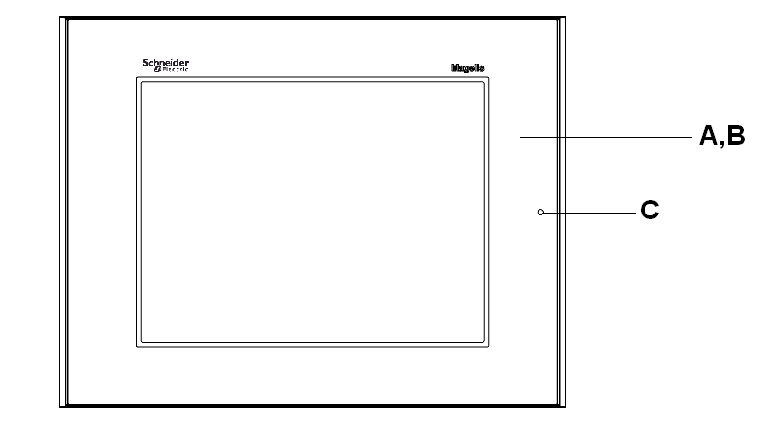
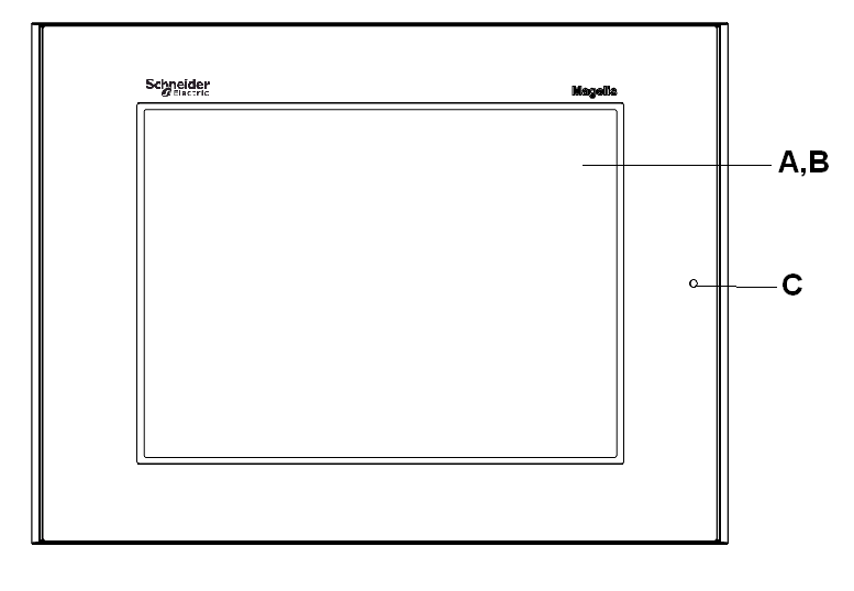
A |
Display: displays user created screens and remote equipment variables. |
|
B |
Touch panel: performs screen change operations and sends data to the host PLC. |
|
C |
Status LED: oGreen (steady): normal operation (power is ON) or OFFLINE operation. oOrange (steady): backlight burnout is detected. oOrange (blinking): during software startup. oRed (steady): when power is turned ON oNot lit: power is OFF |
|
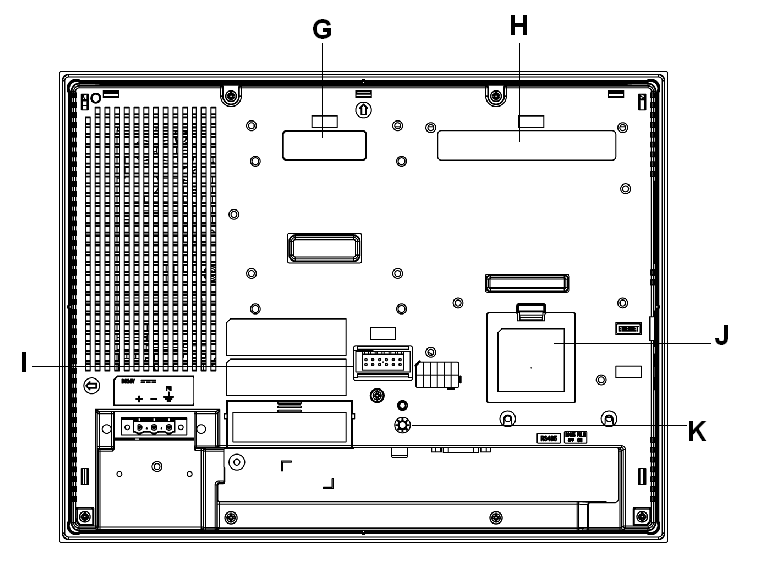
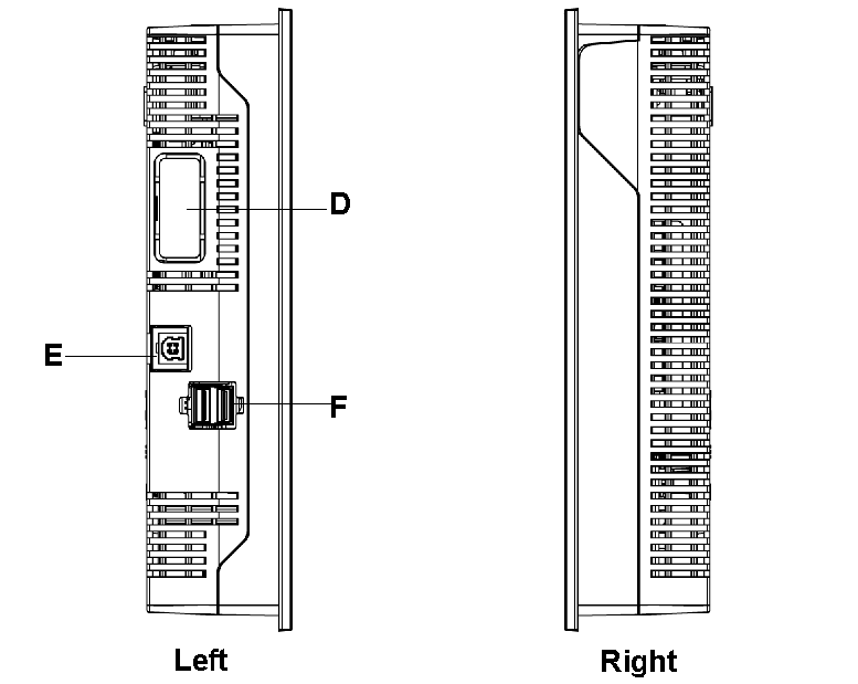
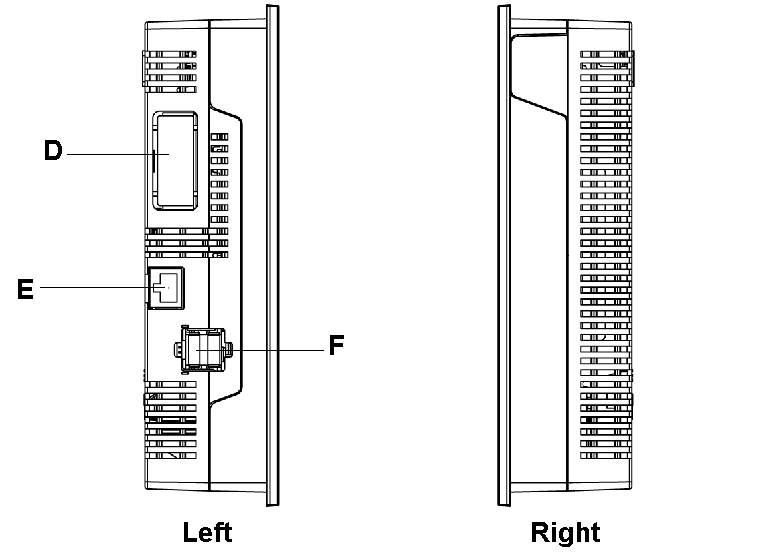
D |
Expansion unit interface: connects expansion units with communication features. |
|
E |
Ethernet interface (LAN) (10Base-T/100Base-TX): RJ-45 connector is used, and the LED turns ON or OFF to indicate the current status. oGreen ON: data transmission available. oGreen OFF: no connection or subsequent loss of communication. oYellow ON: data transmission is occurring. oYellow OFF: no data transmission. |
|
F |
USB host interface (USB1.1) (x2): connects a data transfer cable, USB-compatible printer, peripherals, or a PLC USB terminal port to the XBT GT. The maximum communication distance is 5 m (196.84 in.). |
|
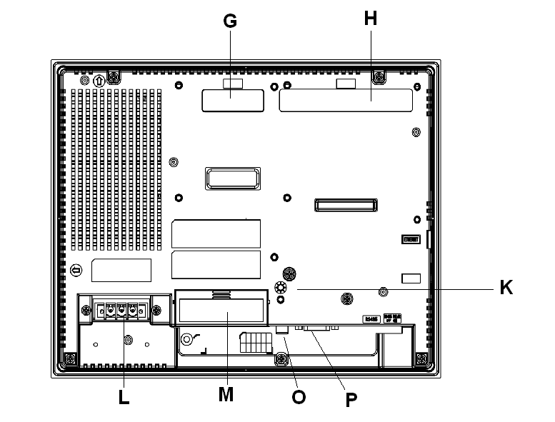
G |
Expansion unit interface (EXT1): connects expansion units with communication features. |
|
H |
Expansion unit interface (EXT2): extends a display function |
|
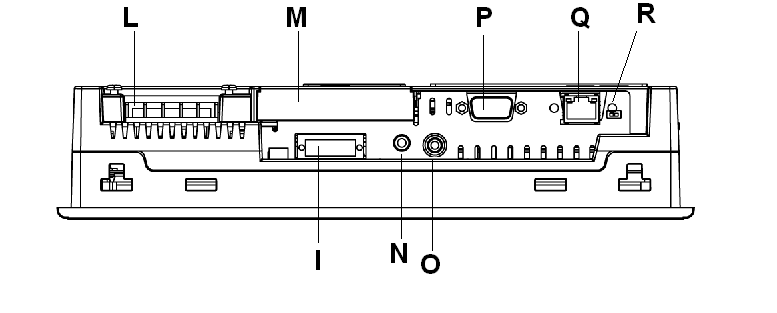
I |
Auxiliary input/output/voice output interface (AUX). This interface is used for: oExternal reset oAlarm output oBuzzer output oSound output |
|
J |
Expansion memory interface cover |
|
K |
CF card access lamp: oGreen ON: the CF card is inserted and the cover is closed, or the CF card is being accessed. oGreen OFF: the CF card is not inserted or is not being accessed. |
|
L |
Power plug connector: power cable is connected to this connector. |
|
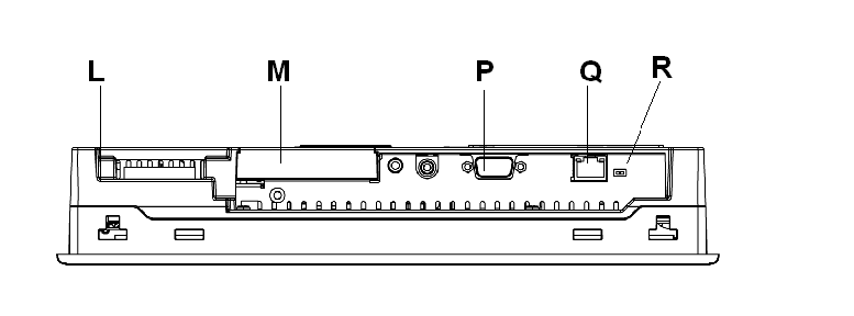
M |
CF card cover: the CF card I/F and DIP Switches are located in the CF card cover (they are accessible when the card cover is open). This cover must be closed when accessing the CF card (See Location of CF Card DIP Switches.) |
|
N |
Audio input interface (L-IN/MIC): this interface is used to connect a microphone (use mini jack connector of 3.5 mm (0.13 in.)) (XBT GT5340 only). |
|
O |
Video input interface: this interface is used to connect a video camera NTSC (59.9 Hz)/PAL (50 Hz). Use with the RCA convertor 75 Ω) (XBT GT5340 only). |
|
P |
Serial interface COM1: connects a RS-232C or RS-422-485 (serial) cable (from the host PLC) to the XBT GT (COM1 port). |
|
Q |
Serial interface COM2: connects a RS-485 (serial) cable (from the host PLC) to the XBT GT (COM2 port). |
|
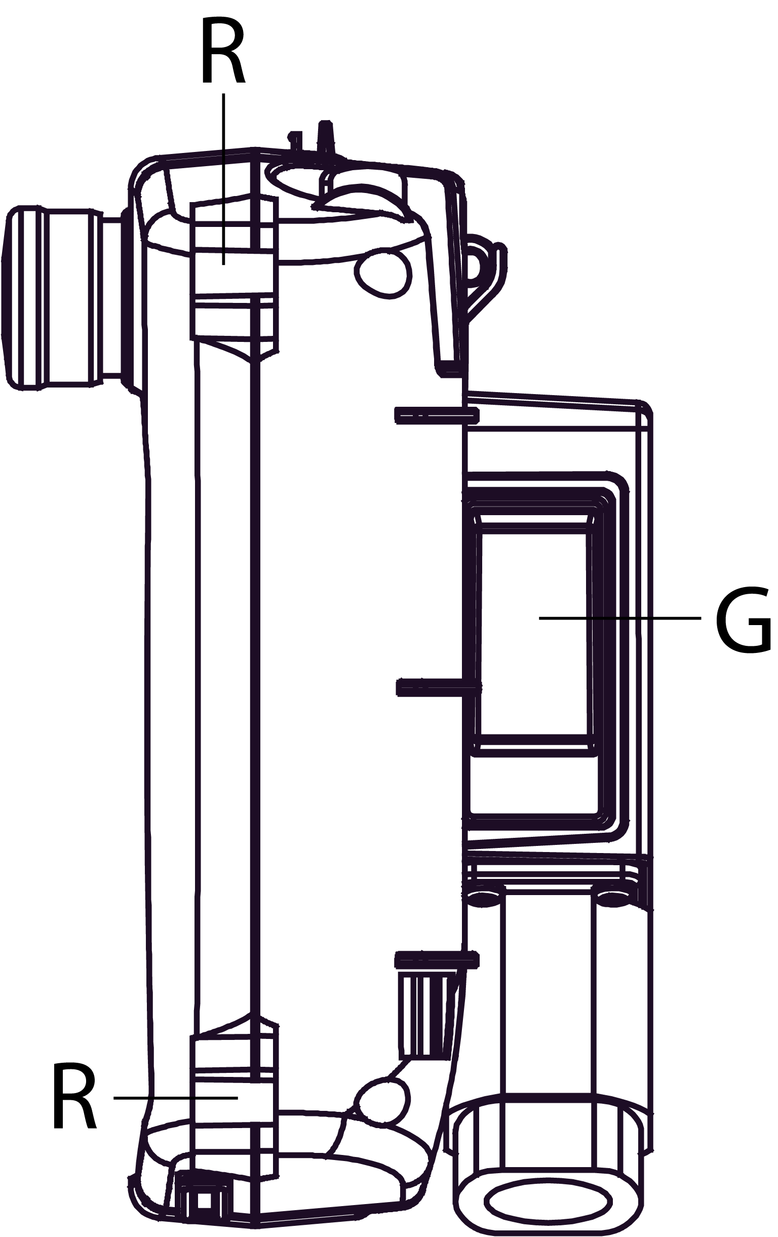
R |
RS-485 line polarization selector switch |
|
Side |
XBT GT6000 series Part Identification |
|---|---|
|
Front |
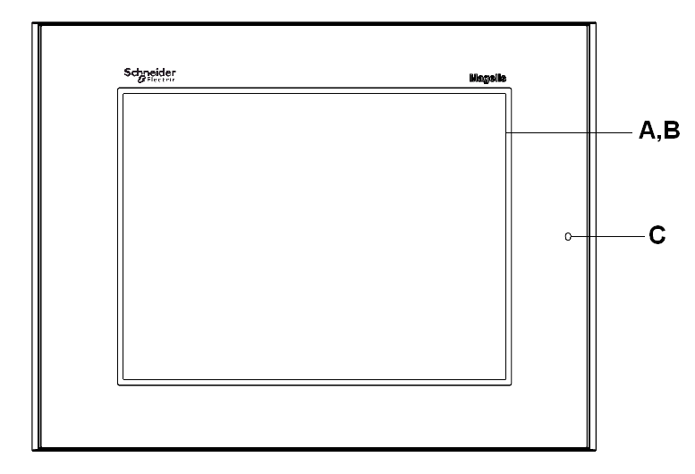
|
|
Rear |
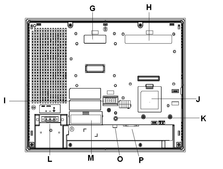
|
|
Left and Right |
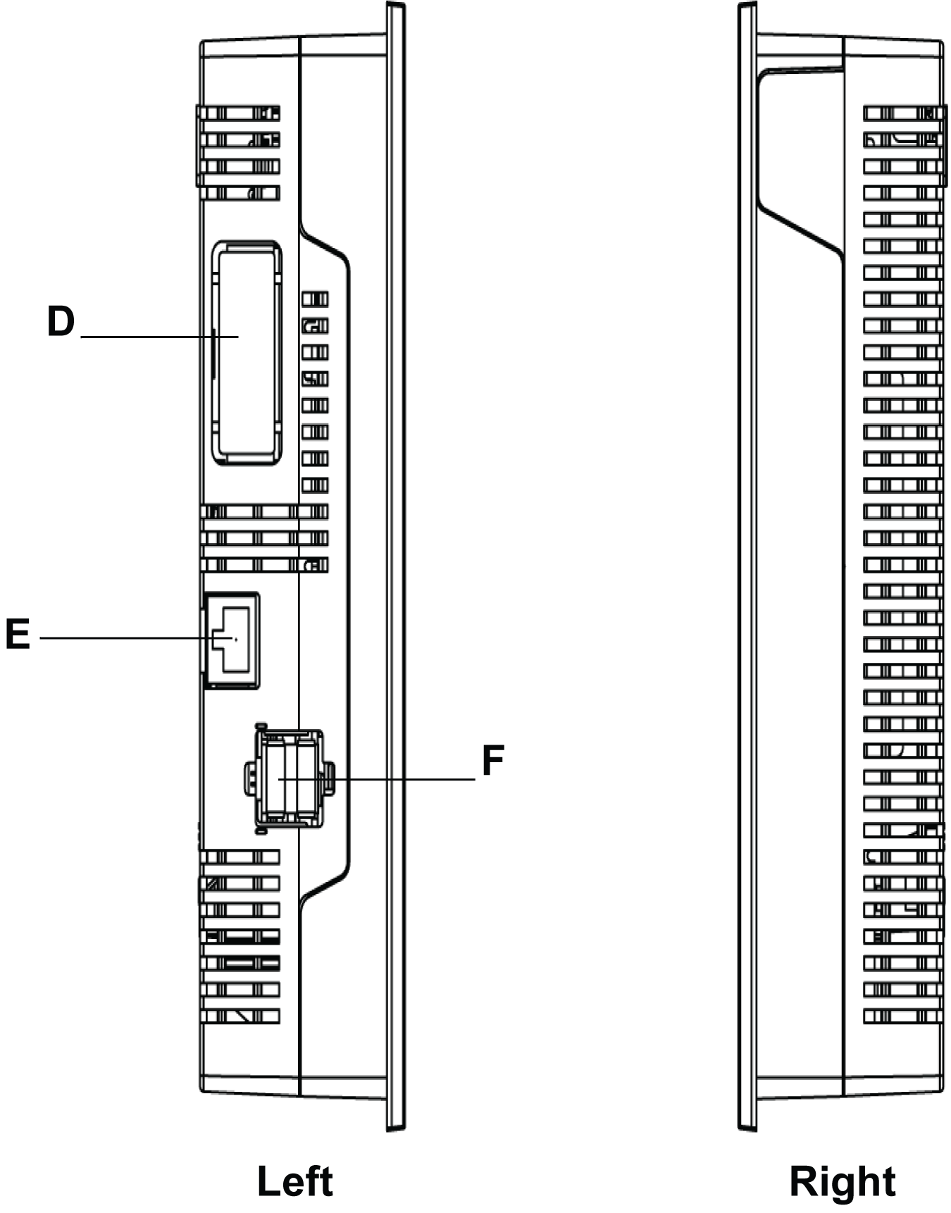
|
|
Bottom |
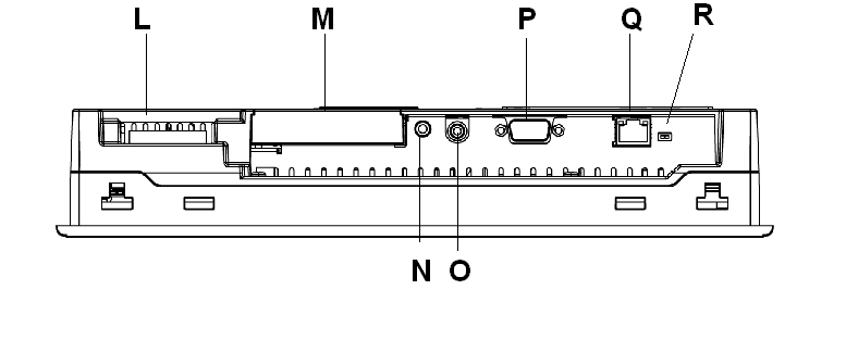
|
|
Part |
Description |
|---|---|
|
A |
Display: displays user created screens and remote equipment variables. |
|
B |
Touch panel: performs screen change operations and sends data to the host PLC. |
|
C |
Status LED: oGreen (steady): normal operation (power is ON) or OFFLINE operation. oOrange (steady): backlight burnout is detected. oOrange (blinking): during software startup. oRed (steady): when power is turned ON oNot lit: power is OFF |
|
D |
Expansion unit interface: connects expansion units with communication features. |
|
E |
Ethernet interface (LAN) (10Base-T/100Base-TX): RJ-45 connector is used, and the LED turns ON or OFF to indicate the current status. oGreen ON: data transmission available. oGreen OFF: no connection or subsequent loss of communication. oYellow ON: data transmission is occurring. oYellow OFF: no data transmission. |
|
F |
USB host interface (USB1.1) (x2): connects a data transfer cable, USB-compatible printer, peripherals, or a PLC USB terminal port to the XBT GT. The maximum communication distance is 5 m (196.84 in.). |
|
G |
Expansion unit interface (EXT1): connects expansion units with communication features. |
|
H |
Expansion unit interface (EXT2): extends a display function |
|
I |
Auxiliary input/output/voice output interface (AUX). This interface is used for: oExternal reset oAlarm output oBuzzer output oSound output |
|
J |
Expansion memory interface cover |
|
K |
CF card access lamp: oGreen ON: the CF card is inserted and the cover is closed, or the CF card is being accessed. oGreen OFF: the CF card is not inserted or is not being accessed. |
|
L |
Power plug connector: the power cable is connected through this connector. |
|
M |
CF card cover: the CF card I/F and DIP switches are located in the CF card cover (they are accessible when the card cover is open). This cover must be closed when accessing the CF card (See Location of CF Card DIP Switches.) |
|
N |
Audio input interface (L-IN/MIC): this interface is used to connect a microphone (use mini jack connector of 3.5 mm (0.13 in.)) (XBT GT6340 only). |
|
O |
Video input interface: this interface is used to connect a video camera NTSC (59.9 Hz)/PAL (50 Hz). Use with the RCA convertor 75 Ω) (XBT GT6340 only). |
|
P |
Serial interface COM1: connects a RS-232C or RS-422-485 (serial) cable (from the host PLC) to the XBT GT (COM1 port). |
|
Q |
Serial interface COM2: connects a RS-485 (serial) cable (from the host PLC) to the XBT GT (COM2 port). |
|
R |
RS-485 line polarization selector switch |
|
Side |
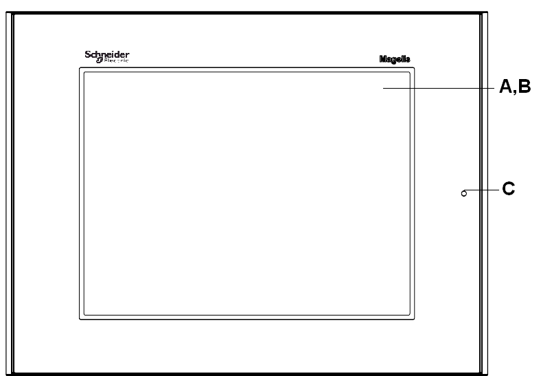
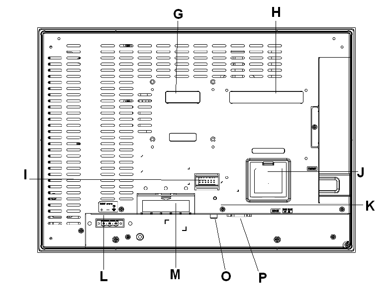
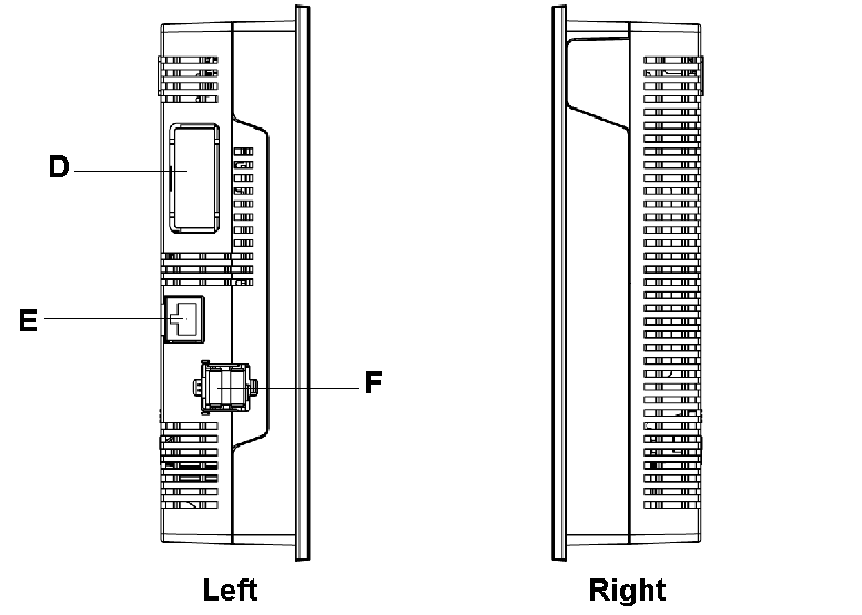
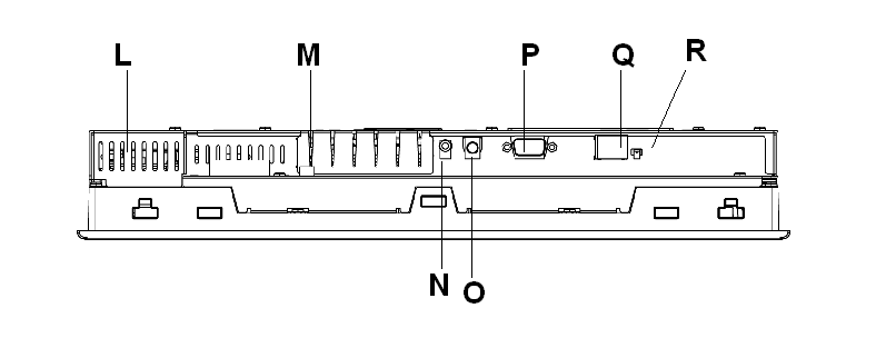
XBT GT7000 series Part Identification |
|---|---|
|
Front |
|
|
Rear |
|
|
Left and Right |
|
|
Bottom |
|
|
Part |
Description |
|---|---|
|
A |
Display: displays user created screens and remote equipment variables. |
|
B |
Touch panel: performs screen change operations and sends data to the host PLC. |
|
C |
Status LED: oGreen (steady): normal operation (power is ON) or OFFLINE operation. oOrange (steady): backlight burnout is detected. oOrange (blinking): during software startup. oRed (steady): when power is turned ON oNot lit: power is OFF |
|
D |
Expansion unit interface: connects expansion units with communication features. |
|
E |
Ethernet interface (LAN) (10Base-T/100Base-TX): RJ-45 connector is used, and the LED turns ON or OFF to indicate the current status. oGreen ON: data transmission available. oGreen OFF: no connection or subsequent loss of communication. oYellow ON: data transmission is occurring. oYellow OFF: no data transmission. |
|
F |
USB host interface (USB1.1) (x2): connects a data transfer cable, USB-compatible printer, peripherals, or a PLC USB terminal port to the XBT GT. The maximum communication distance is 5 m (196.84 in.). |
|
G |
Expansion unit interface (EXT1): connects expansion units with communication features. |
|
H |
Expansion unit interface (EXT1): extends a display function |
|
I |
Auxiliary input/output/voice output interface (AUX) This interface is used for: oExternal reset oAlarm output oBuzzer output oSound output |
|
J |
Expansion memory interface cover |
|
K |
CF card access lamp: oGreen ON: the CF card is inserted and the cover is closed, or the CF card is being accessed. oGreen OFF: the CF card is not inserted or is not being accessed. |
|
L |
Power plug connector: power cable is connected to this connector. |
|
M |
CF card cover: the CF card I/F and DIP switches are located in the CF card cover (they are accessible when the card cover is open). This cover must be closed when accessing the CF card (See Location of CF Card DIP Switches.) |
|
N |
Audio input interface (L-IN/MIC): this interface is used to connect a microphone (use mini jack connector of 3.5 mm (0.13 in.)) (XBT GT7340 only). |
|
O |
Video input interface: this interface is used to connect a video camera NTSC (59.9 Hz)/PAL (50 Hz). Use with the RCA convertor 75 Ω) (XBT GT7340 only). |
|
P |
Serial interface COM1: connects a RS-232C or RS-422-485 (serial) cable (from the host PLC) to the XBT GT (COM1 port). |
|
Q |
Serial interface COM2: connects a RS-485 (serial) cable (from the host PLC) to the XBT GT (COM2 port). |
|
R |
RS-485 line polarization selector switch. |
|
Side |
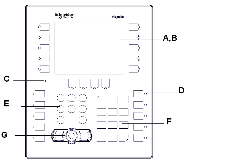
XBT GK2000 series Part Identification |
|---|---|
|
Front |
|
|
Part |
Description |
|---|---|
|
A |
Display: displays user created screens and remote equipment variables. |
|
B |
Touch panel: performs screen change operations and sends data to the host PLC |
|
C |
Status LED: oGreen (steady): normal operation (power is ON) or OFFLINE operation. oOrange (steady): backlight burnout is detected. oOrange (blinking): during software startup. oNot lit: power is OFF |
|
D |
Function keys (R1 to R10, R21 to R24, F1 to F10): used for function keys. |
|
E |
System keypad: controls various system operations. |
|
F |
Alphanumeric keypad: enables the user to input characters or numeric values. |
|
G |
Mouse pointer: the pointer moves the cursor and the buttons activate objects and enable data inputs. |
|
Side |
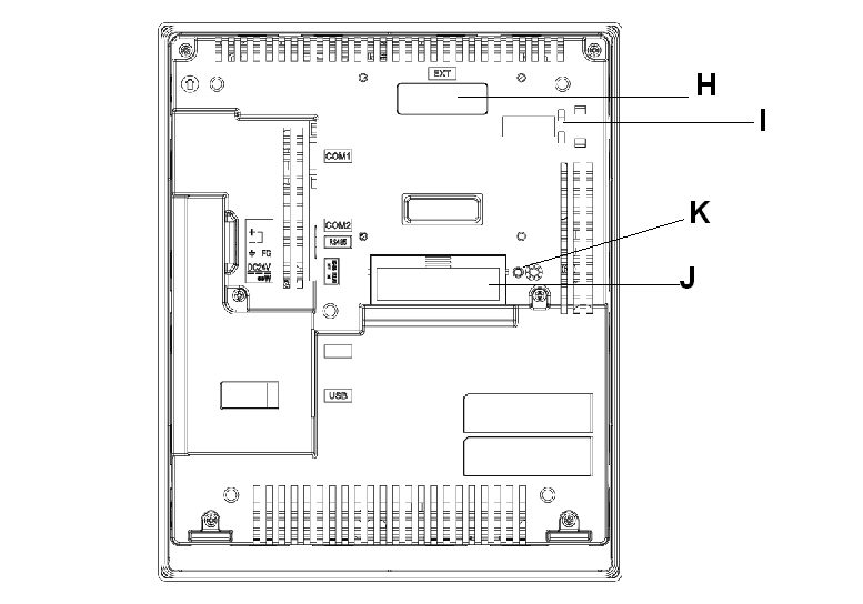
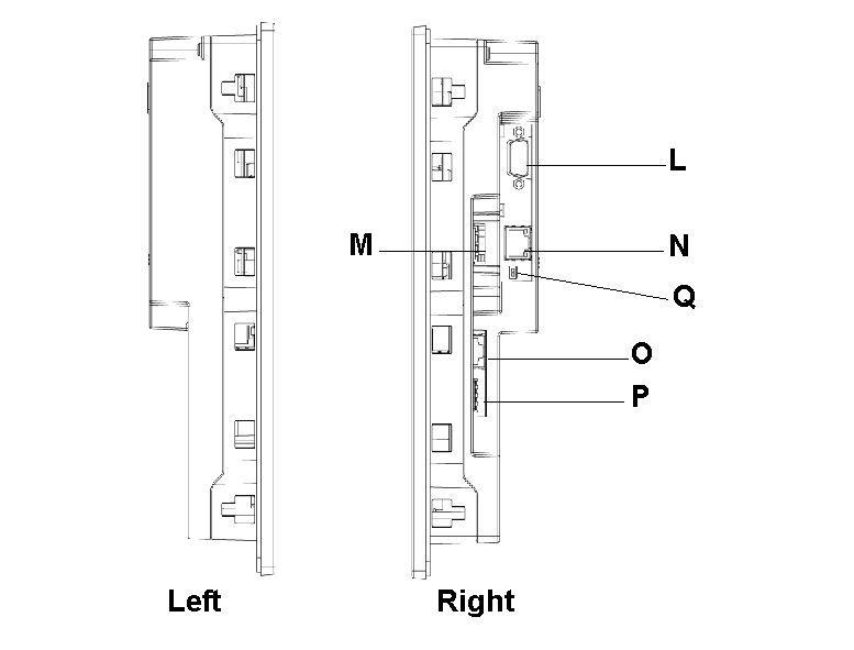
XBT GK2000 series Part Identification |
|---|---|
|
Rear |
|
|
Left and Right |
|
|
Bottom |

|
|
Part |
Description |
|---|---|
|
H |
Expansion unit interface (EXT1): connects expansion units with communication features. |
|
I |
Ethernet indicator (except XBT GK2120): the LED turns ON or OFF to indicate the current status. oGreen ON: Data transmission available. oGreen OFF: No connection or subsequent loss of communication. oYellow ON: Data transmission is occurring. oYellow OFF: No data transmission. |
|
J |
CF card cover: the CF card socket and DIP Switches are located under the CF card cover (they are accessible when the card cover is open). This cover must be closed when accessing the CF card (See Location of CF Card DIP Switches.) |
|
K |
CF card access lamp: oGreen ON: the CF card is inserted and the cover is closed, or the CF card is being accessed. oGreen OFF: the CF card is not inserted or is not being accessed. |
|
L |
Serial interface COM1: connects a RS-232C or RS-422-485 (Serial) cable (from the host PLC) to the unit (COM1 port). |
|
M |
Power input terminal block: connects the units power cable’s input and ground wires to the unit. |
|
N |
Serial interface COM2: connects a RS-485 (serial) cable (from the host PLC) to the unit (RS-485 port). |
|
O |
Ethernet interface (10Base-T/100Base-TX) (except XBT GK2120): RJ-45 connector is used. |
|
P |
USB host interfaces (USB1.1): connects a data transfer cable, USB-compatible printer, peripherals, or a PLC USB terminal port to the XBT GK. The maximum communication distance is 5 m (196.84 in.). |
|
Q |
RS-485 line polarization selector switch. |
|
Side |
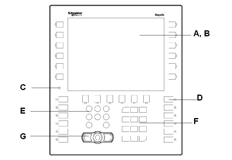
XBT GK5330 Part Identification |
|---|---|
|
Front |
|
|
Part |
Description |
|---|---|
|
A |
Display: displays user created screens and remote equipment variables. |
|
B |
Touch panel: performs screen change operations and sends data to the host PLC |
|
C |
Status LED: oGreen (steady): normal operation (power is ON) or OFFLINE operation. oOrange (steady): backlight burnout is detected. oOrange (blinking): during software startup. oNot lit: power is OFF |
|
D |
Function keys (R1 to R12, R21 to R26, F1 to F12): used for function keys. |
|
E |
System keypad: controls various system operations. |
|
F |
Alphanumeric keypad: enables the user to input characters or numeric values. |
|
G |
Mouse pointer: the pointer moves the cursor and the buttons activate objects and enable data inputs. |
|
Side |
XBT GK5330 Part Identification |
|---|---|
|
Rear |
|
|
Left and Right |
|
|
Bottom |

|
|
Part |
Description |
|---|---|
|
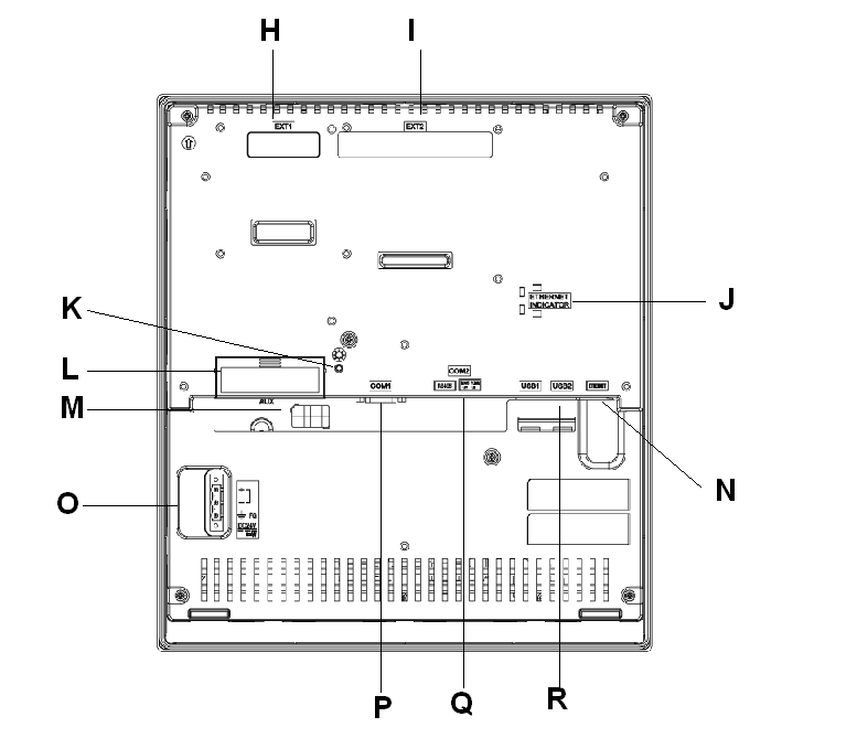
H |
Expansion unit interface (EXT1): connects expansion units with communication features. |
|
I |
Expansion unit interface (EXT2): connects expansion units with communication features. |
|
J |
Ethernet indicator: the LED turns ON or OFF to indicate the current status. oGreen ON: data transmission available. oGreen OFF: no connection or subsequent loss of communication. oYellow ON: data transmission is occurring. oYellow OFF: no data transmission. |
|
K |
CF card access lamp: oGreen ON: the CF card is inserted and the cover is closed, or the CF card is being accessed. oGreen OFF: the CF card is not inserted or is not being accessed. |
|
L |
CF card cover: The CF card socket and DIP switches are located in the CF card cover (they are accessible when the card cover is open). This cover must be closed when accessing the CF card (See Location of CF Card DIP Switches.) |
|
M |
Auxiliary input/output/voice output interface (AUX) This interface is used for: oExternal reset oAlarm output oBuzzer output oSound output |
|
N |
Ethernet interface (10Base-T/100Base-TX): RJ-45 connector is used. |
|
O |
Power input terminal block: connects the XBT GK power cable’s input and ground wires to the unit. |
|
P |
Serial interface COM1: connects a RS-232C or RS-422 (serial) cable (from the host PLC) to the unit (COM1 port). |
|
Q |
Serial interface COM2: connects a RS-485 (serial) cable (from the host PLC) to the unit (RS-485 port). |
|
R |
USB host interfaces (USB1.1) (x2): connects a data transfer cable, USB-compatible printer, peripherals, or a PLC USB terminal port to the XBT GK. The maximum communication distance is 5 m (196.84 in.). |
|
S |
RS-485 line polarization selector switch. |
|
Side |
XBT GH2460 Part Identification |
|---|---|
|
Front |
|
|
Part |
Description |
|---|---|
|
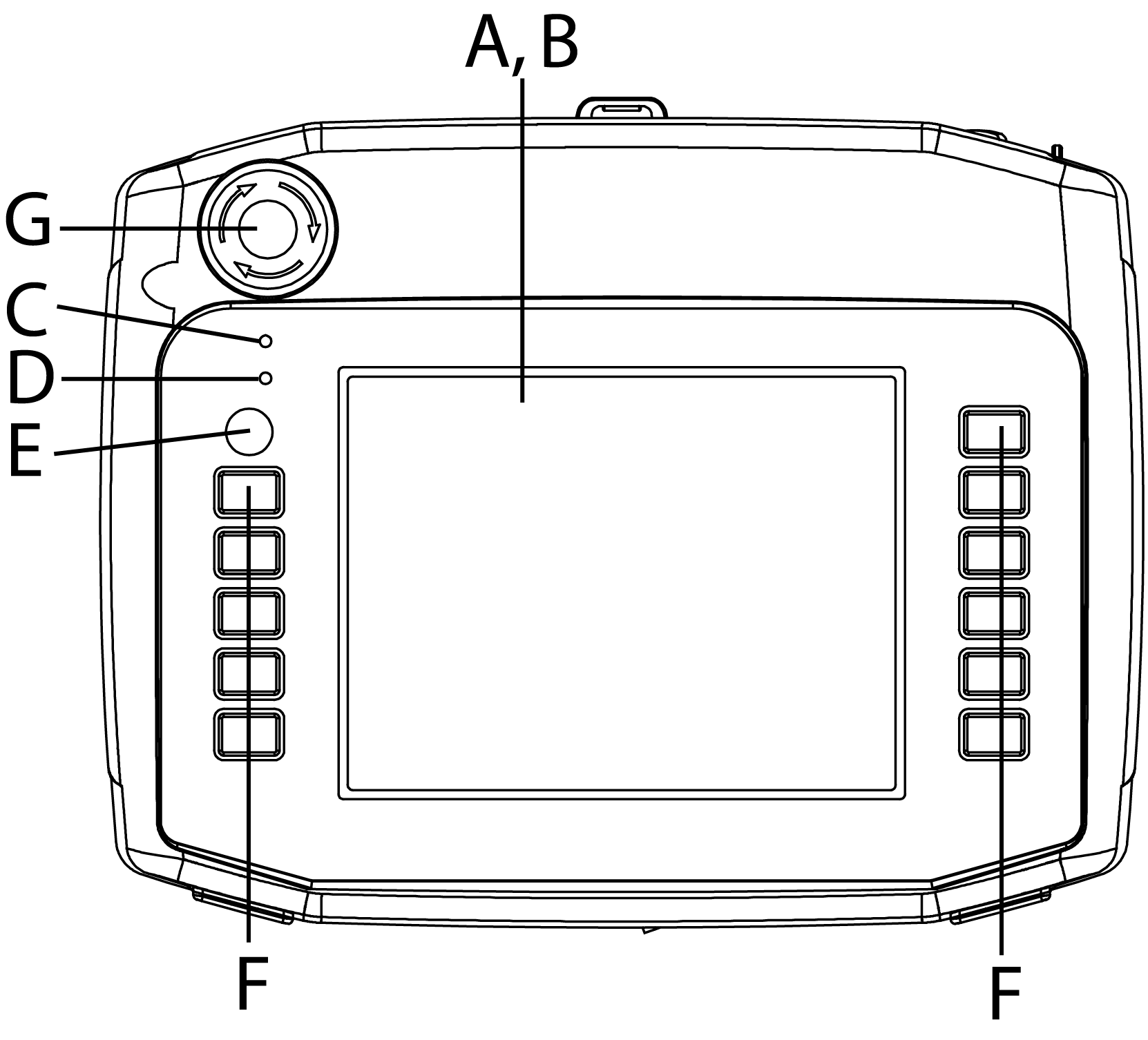
A |
Display: displays user created screens and remote equipment variables. |
|
B |
Touch panel: performs screen change operations and sends data to the host PLC |
|
C |
Status LED: oGreen ON: normal operation (power is ON) or OFFLINE operation. oOrange ON: backlight burnout is detected. oOrange (blinking): during software startup. oNot lit: power is OFF. |
|
D |
Operation LED: oGreen ON: the Operation switch is ON. oNot lit: the Operation switch is OFF. |
|
E |
Operation Switch: When this switch is pressed, the XBT GH unit can accept input from the touch screen and function switches. |
|
F |
Function Switches: Functions are set up with the screen design software. For details see the Vijeo-Designer online help. |
|
G |
Emergency Switch |
|
Side |
XBT GH2460 Part Identification |
|---|---|
|
Rear |
|
|
Right |
|
|
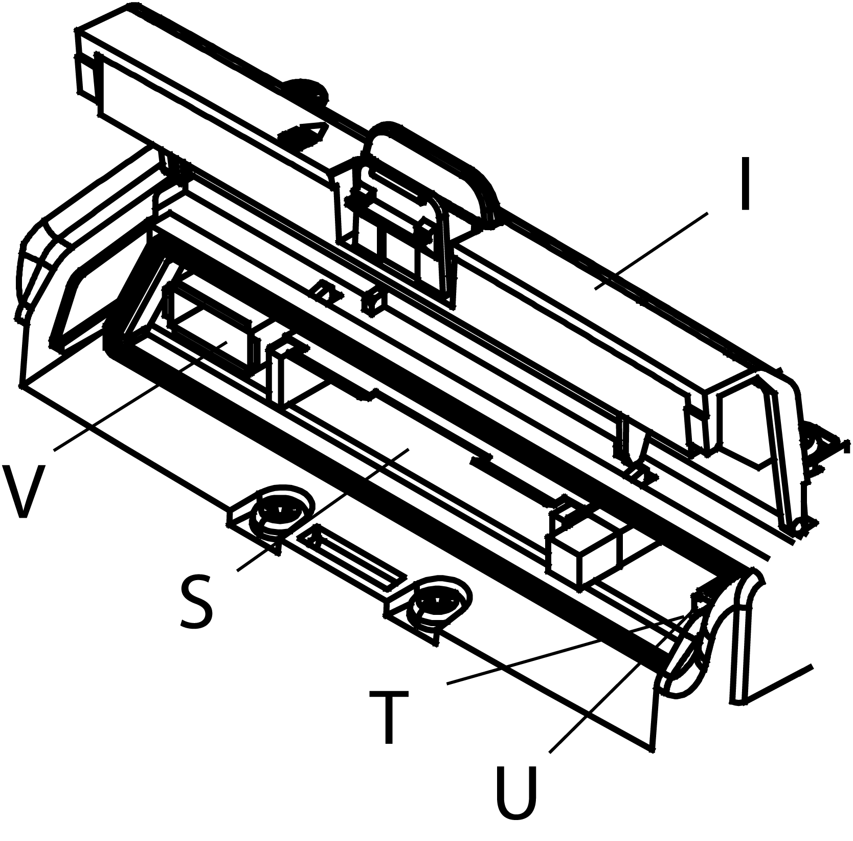
CF Card Cover Open |
|
|
Part |
Description |
|---|---|
|
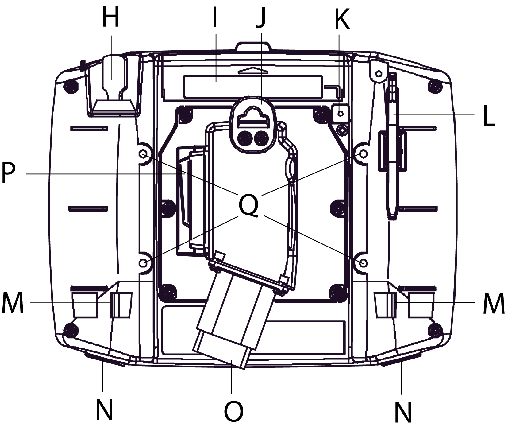
H |
Key Switch: Turning the key turns ON/OFF the XBT GH unit power supply. |
|
I |
CF card cover: The CF card socket and DIP switches are located in the CF card cover (they are accessible when the card cover is open). This cover must be closed when accessing the CF card (See Location of CF Card DIP Switches.) |
|
J |
Hook: A hook for temporarily hanging the XBT GH unit on a wall. Note: The following is recommended to be used as pairs for this hook: oA Æ7 or less, rod-shaped or S-shaped hook. oM4 pan-head machine screw, which head diameter is Æ7 or less. oPanel thickness: 1...1.6mm (0.04...0.06 in.) oPanel width: 14mm (0.55 in.) |
|
K |
CF card access lamp: oGreen ON: the CF card is inserted and the cover is closed, or the CF card is being accessed. oGreen OFF: the CF card is not inserted or is not being accessed. |
|
L |
Stylus: Use the stylus for entering data to the touch screen interface. |
|
M |
Hand Strap Attachment Slots (2) |
|
N |
Insertion hole (with cover) for Function Switch Sheet (2) |
|
O |
XBT GH Cable Connector (with Connector Cover) |
|
P |
3-Position Enable Switch: The switch provides three positions: oThe switch is not pressed (released). oThe switch is pressed to the intermediate position. oThe switch is pressed to the innermost position (fully pressed). |
|
Q |
Wall Adapter Attachment Slots: To mount the XBT GH unit to a panel or commercially available arm, attach the dedicated wall-hanging adapter (optional) to this slot. |
|
R |
Neck Strap Attachment Slots (4) |
|
S |
CF card interface: Insert the CF card in this slot. |
|
T |
LAN status LED: The LED turns ON or OFF to indicate the current status of the Ethernet transmission interface (10BASE-T/100BASE-TX). oGreen ON: Data transmission available. oGreen Flashing: Data transmission is occurring. oGreen OFF: No connection or subsequent loss of communication. oOrange ON: Connecting with 100BASE-TX. oOrange OFF: Connecting with 100BASE-TX or No connection. |
|
U |
Dip Switches: After inserting a CF Card, be sure to turn ON DIP Switch 4, and close the CF Card cover before using the GP unit. For more information, see “CF Card DIP Switches” on page 13. |
|
V |
USB Host Interface: Complies with USB 1.1. Uses a “TYPE-A” connector. Power supply voltage: DC5 V±5%, Output current: 500 mA (max). Connect to the transfer cable, storage device (USB memory, CF Card reader), etc. Maximum communication distance: 5 m (196.84 in.) |