Shifting, Rotating, and Scaling the Coordinate System
Function:
the G code commands G54, G55 and G56 shift, rotate, and scale the decoder coordinate system that is used internally by the decoder POU SMC_NCDecoder. The coordinate transformations are calculated for all path elements during the decoding operation (during the execution of the function block instance SMC_NCDecoder).
The G code command G53 resets the decoder coordinate system to the original position, orientation, and scaling (corresponding to the machine coordinate system).
Note
You shift and rotate the decoder coordinate system in order to ruse the G code of the same path elements that differ only by position, orientation, or scaling.
Coordinate systems: MCS and DCS
The machine coordinate system (MCS) is predefined by the used kinematics which determine its position and orientation.
The decoder coordinate system (DCS) manages the decoder (function block instance SMC_NCDecoder). All coordinate information for motion commands are interpreted in this coordinate system. This affects the target position of a movement (X/Y/Z), as well as an arc midpoint (I/J/K) or a plane that is set with G15/G16/G17/G18/G19.
The DCS is programmed with the commands G53/G54/G55/G56. You can rotate, shift, and scale the DCS with respect to the machine coordinate system, and therefore adapt the position, orientation, and scaling in the G code file any number of times. You program the path elements relative to the DCS. For example, this can be an advantage for the same path elements in different positions and orientations.
The CNC program is decoded when the function block instance SMC_NCDecoder is executed. The decoder receives the information from its eOriConv input about whether A/B/C are treated as additional axes or as orientation values. The coordinates of the path elements are transformed accordingly. The start and target positions and the plane for arcs are specified in the generated GeoInfo objects always relative to the machine coordinate system. Therefore, the decoder POU manages an active coordinate system. Initially (after the rising Execute edge), the decoder coordinate system corresponds to the machine coordinate system.
|
SMC_NCDecoder.eOriConf = SMC_ORI_CONVENTION.ADDAXES |
No orientation convention specified. The contents of the G code word A/B/C is interpreted as an shift value. |
|
SMC_NCDecoder.eOriConf = SMC_ORI_CONVENTION.ZYZ |
The orientation convention is the standard Y convention (Z, Y', Z''). The contents of the G code word A/B/C is interpreted as an angle value. |
|
SMC_NCDecoder.eOriConf = SMC_ORI_CONVENTION.ZYX |
The orientation convention is the yaw-pitch-roll convention (Z, Y', X''). The contents of the G code word A/B/C is interpreted as an angle value. |
|
SMC_NCDecoder.eOriConf = SMC_ORI_CONVENTION.XYZ |
The orientation convention is the XYZ convention (X, Y', Z''). The contents of the G code word A/B/C is interpreted as an angle value. |
|
G code |
Description |
|
G53 |
Resets the decoder coordinate system. The DCS is reset to the same position and orientation as the MCS. |
|
G54 |
Absolute shift, rotation, and scaling of the DCS. The values are related to the MCS: If an orientation convention is not specified (SMC_NCDecoder.eOriConf = SMC_ORI_CONVENTION.ADDAXES), then the command results in a shift only along the axes X/Y/Z/A/B/C and on all additional linear axes P/Q/U/V/W. Therefore, a shift can also be programmed along the A/B/C axes. If an orientation convention is specified, then the command results in a shift also along the axes X/Y/Z and along the additional linear axes P/Q/U/V/W. In addition, the coordinate axes are rotated. Then the orientation convention provides the rotation order and the G code words A/B/C give the angles of rotation in degrees (0°-360°). |
|
G55 |
Relative shift, rotation, and scaling of the DCS to its current position and orientation. Therefore the values are relative to the current DCS origin and interpreted in the direction of the current coordinate axes of the DCS. An additional shift/rotation is added with respect to the machine coordinate system. If an orientation convention is not specified, then the command results in a relative shift only along the axes X/Y/Z/A/B/C and on all additional linear axes P/Q/U/V/W. Therefore, a shift can also be programmed along the A/B/C axes. If an orientation convention is specified, then the command results in a relative shift also along the axes X/Y/Z and along the additional linear axes P/Q/U/V/W. But above all, the coordinate axes are rotated further. Then the orientation convention provides the rotation order and the G code words A/B/C give the angles of rotation. |
|
G56 |
Resets the reference point of the decoder coordinate system. the current orientation, position, and scaling of the DCS is set as a reference. Tip: If the reference point is X0 Y0 Z0 A0 B0 C0, then the DCS is set identically to the current position and orientation. |
Syntax
G53
G54 X Y Z A B C I J K P Q U V W
G55 X Y Z A B C I J K P Q U V W
G56 X Y Z A B C I J K P Q U V W
|
G code word |
Description |
|
X |
Value around which the decoder coordinate system is shifted. |
|
Y |
|
|
Z |
|
|
A |
If the input is eOriConf = SMC_ORI_CONVENTION.ADDAXES at SMC_NCDecoder, then the value is given in units how far the respective additional axis is shifted. Therefore, the parameter defines the shift for each axis of the decoder coordinate system with respect to the machine coordinate system. If the input eOriConf is SMC_ORI_CONVENTION.ZYZ, SMC_ORI_CONVENTION.ZYX, or SMC_ORI_CONVENTION.XYZ at SMC_NCDecoder, then an orientation convention is provided. In this case, the values given here are automatically interpreted as degrees and determine by how much the axes of the decoder coordinate system are rotated with respect to the machine coordinate system. Therefore, you define the rotation of the main axes according to the orientation convention. Note: When programming the DCS rotation, the angles of rotation should always be specified in A/B/C for all three axes. A missing angle of rotation causes an error when decoding (SMC_DEC_DCS_NOT_ALL_OF_ABC_GIVEN). |
|
B |
|
|
C |
|
|
I |
Scaling in direction X. Example: 10 for stretching by a factor of 10. |
|
J |
Scaling in direction Y. Example: 10 for stretching by a factor of 10. |
|
K |
Scaling in direction Z. Example: 10 for stretching by a factor of 10. |
|
P |
Value around which the additional axis of the decoder coordinate system is shifted. |
|
Q |
|
|
U |
|
|
V |
|
|
W |
Set the input eOriConv of the function block instance SMC_NCDecoder to SMC_ORI_CONVENTION.ADDAXES.
⇒ The DCS can be shifted. A rotation is not possible.
Program the CNC path. Specify the position shift of the DCS first.
Example: C54 X10 Y10 Z10 A30 B30 C30
⇒ The X/Y/Z/A/B/C axes of the DCS are shifted.
Example
Absolute offset
N10 G0 X100 Y100 F100
N20 G54 X50 Y50 (offset at 50/50)
N30 G1 X0 Y0 (travel to 50/50)
N40 G54 X100 Y100 (offset at 100/100)
N50 G1 X0 Y0 (travel to 100/100)
N60 G53 (offset at 0)
N70 G1 X0 Y0 (travel to 0/0)
Current position as offset
N0 G0 X100 Y100 F100
N10 G56 X0 Y0 (current position 100/100 is 0/0)
N20 G1 X10 (travel to 110/100)
N30 G56 X20 Y0 (current position 110/100 is 20/0)
N40 G1 X0 (travel to 90/100)
Adapt offset by value
N0 G54 X10 Y20 Z30 U7 (offset: X=10, Y=20, Z=30, U=7)
N10 G55 X-10 U7 (offset: X=0, Y=20, Z=30, U=14)
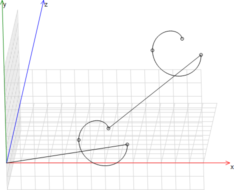
Same path elements in two positions
N05 G17
N10 G54 X10 Y10 Z10
N20 G01 X6.574 Y-10 Z-1.961 I8.287 J-0.000
N30 G02 X-0.480 Y-10 Z0.008 I-3.527 J4.988E-05
N040 G02 X3.418 Y-9.806 Z4.482 I1.949 J0.097
N50 G55 X10 Y10 Z10
N60 G01 X6.574 Y-10 Z-1.961 I8.287 J-0.000
N70 G02 X-0.480 Y-10 Z0.008 I-3.527 J4.988E-05
N80 G02 X3.418 Y-9.806 Z4.482 I1.949 J0.097
Set the input eOriConv of the function block instance SMC_NCDecoder to the desired orientation convention (for example, SMC_ORI_CONVENTION.ZYZ).
⇒ The orientation convention and the rotation order of the X/Y/Z axes of the DCS are programmed. For SMC_ORI_CONVENTION.ZYZ, the rotation order is ZY'Z'' and corresponds to the standard Y-convention.
Note: As long as the input eOriConv contains an orientation convention and not the value SMC_ORI_CONVENTION.ADDAXES, the values of the words A/B/C are interpreted as angle values for the rotation for the G code commands G54/G55/G56.
Program the CNC path. Specify the position shift and rotation of the DCS first.
Example: C54 X10 Y10 Z10 A30 B30 C30
⇒ The values of the words A/B/C provide the direction of rotation and the angle in degrees. The coordinate system is rotated accordingly. The values of the words X/Y/Z define the shift.
Note: When programming the DCS rotation, the angles of rotation should always be specified in A/B/C for all three axes. A missing angle of rotation causes an error when decoding (SMC_DEC_DCS_NOT_ALL_OF_ABC_GIVEN).
If the input eOriConv of the function block instance SMC_NCDecoder contains the value SMC_ORI_CONVENTION.ADDAXES, then rotating the DCS is not possible. The values in G54/G55/G56 are interpreted as additional spline axis values. Shifting is possible.
Examples
The orientation convention was defined in the examples as the standard Y-convention (eOriConv = SMC_ORI_CONVENTION.ZYZ). In general for G54: X/Y/Z/A/B/C/P/Q/V/W provides an absolute value in the MCS. G55: X/Y/Z/A/B/C/P/Q/V/W provides a relative value in the DCS. G56: X/Y/Z/A/B/C/P/Q/V/W provides an absolute new value in the DCS.
Absolute orientation with G54
N01 G54 X10 A30 B0 C0
G54 causes a shift and rotation. The position and orientation are provided absolute to the MCS.
Relative orientation with G55
N01 G54 X10 A30 B0 C0 (with respect to the MCS)
N02 G55 Y10 A0 B30 C0 (with respect to the DCS as defined in 01)
G54 results in a shift of 10 units in the x-direction and a 30° rotation about the z-axis absolute to the MCS. In block 02, the DCS is shifted an additional 10 units in the direction of the rotated y-axis and then rotated an additional 30° about the rotated y-axis. Therefore, the transformation in block 02 is relative to the transformation in block 01.
Referencing with respect to the current orientation with G56
N01 G01 X10 A10 B90 C10 (Orientation is A=10°, B=90°, C=10°)
N02 G56 A0 B0 C0 (The DCS is set to X=10, A=10°, B=90°, C=10°)
G56 causes the current orientation of the DCS (programmed in block 01 in the example) to be set as a reference.
Example: Arc
N0 G17
N0 G54 A0 B90 C0
The selected circle plane is interpreted relative to the DCS. In the example, the xy-plane is selected with G17 and then the DCS is rotated 90° about the y-axis. The the selected plane in the DCS is the xy-plane as before. This corresponds to that of the xz-plane in the MCS.
With G17, the xy-plane is selected. Then the DCS is rotated by 90°. This causes the xy-plane to be activated in the DCS as before. This corresponds to the xy-plane in the MCS.
Note
In 2.5D mode (G15), rotation is permitted about the z-axis only. Rotation about another axis causes an error that is issued by the decoder (SMC_DEC_DCS_2D_NOT_IN_XY_PLANE). Therefore, the xy-plane of the MCS always remains set in 2.5D mode.
Notice
If a rotation is programmed after an unequal scaling, then clipping can occur. In this case, the error SMC_DEC_ROTATION_AFFECTS_SCALING is not issued.
Notice
All three scaling factors have to be specified or none at all.
Absolute scaling
Syntax: G54 I<i> J<j> K<k>
A coordinate system can be stretched or compressed in the three spatial directions X/Y/Z independently of each other. You can specify a factor for each direction. Specify the scaling factor for X in I, Y in J, and Z in K. A scaling factor > 1 stretches. A scaling factor < 1 compresses.
Stretching 10x:
N01 G01 X10
N02 G54 A90 B0 C0 I10 J1 K1
N03 G01 X10 Y20
N04 G01 X5 Y10
All target points are stretched 10x in the direction of the rotated x-axis.
The following code generates the same path:
N01 G01 X10
N02 G01 X-20 Y100
N03 G01 X-10 Y50.
If neither I nor J nor K are specified, then the previously set value remains unchanged.
N01 G54 I10 J1 K1
N02 G54 X1
N03 G01 X10
The same path is achieved with the following code:
N01 G01 X101
Relative scaling
Syntax: G55 I<i> J<j> K<k>
A scaling factor > 1 stretches. A scaling factor < 1 compresses. The scaling factors are multiplied.
Stretching 100x:
N01 G54 I10 J1 K1
N02 G55 I10 J1 K1
N03 G01 X10 Y20
N04 G01 X5 Y10
The following code results in the same scaling:
N01 G55 I100 J1 K1
Circular scaling
The scaling of an arc is valid only if the element is still an arc (not an ellipse) after the scaling.
Valid paths result:
If all three scaling factors are the same value.
If the circular plane is one of the primary planes of the DCS and the corresponding two scale factors are the same values.
Mirroring the coordinate system
An absolute scaling with negative scaling factors in I, J, or K results in mirroring of the current coordinate system.
Negative scale factor
G54 A30 B0 C0 I-1 J1 K1