Position Control on the PLC with SM_Drive_PosControl
Refer to the sample project PosControl.project in the installation directory of CODESYS SoftMotion.
In most cases, a servo controller takes over the position control of the drive, as well as the current and rotational speed control. However, there are also use cases in which the controller takes over the position control of the axis. This example demonstrates how a speed controlled device (e.g. frequency converter with position feedback) is position-controlled by CODESYS SoftMotion.
The requirement is a device that is controlled by the set velocity and returns its current position. In this example, a 10V analog output terminal EL4031 is used with a signal that is used as a speed setpoint for a frequency converter. An encoder terminal EL5101 is used for position feedback.
Controlling the axis position with SM_Drive_PosControl
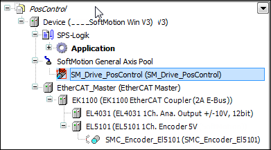
Add a position-controlled axis of type SM_Drive_PosControl to the device tree below SoftMotion General Axis Pool.
Add the terminals for the analog terminal (EL4031) and the encoder (EL5101) to the device tree.
⇒ 
Note
The device descriptions of the fieldbus devices have to be downloaded and installed from the manufacturer.
Open the SM_Drive_PosControl device in the editor and specify the general parameter Modulo with value 360.0 in the General tab.
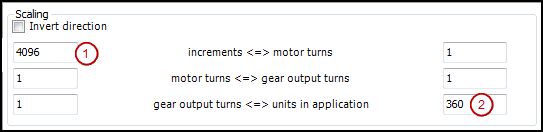
Switch to the Scaling/Mapping tab. The number of increments per motor rotation is taken from the from the encoder data sheet. In this example, 4096 increments (1) are one motor rotation. As you are working with angular degrees in the application, you specify the value 360 (2) for Units in the application.
⇒ 
Switch to the Position control tab and specify the following parameters:

D 2.0
The dead time determines the number of cycles that the received actual position (encoder) is displaced to the set position of the axis. The dead time depends on the used components and must be determined by trial and error.
Kp 0.0
The constant of proportionality is the factor by which the position error (the deviation between set and actual position) is multiplied to be added later to the set velocity. Now set this value to 0. You will determine the value experimentally at a later time.
Bit width: 16
The bit width of the actual value is received depending on the used components and can be set as 16, 24, or 32-bit values. Set the value to 16 because the used components yield the position as UINT.
![]() max
max
Let the position error monitoring switch off. You can switch it back on again if necessary. Activate the check box and specify a maximum permitted drag error. If this value is exceeded during operation, then the axis goes into an error state.
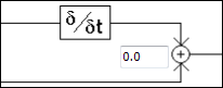
The parameter has the value 0 and should be changed only in very special cases. It defines the relationship between the set velocity and the derivation of the position. The value range is 0 to 1:
0: The value of fSetVelocity is used as the source.
1: The numeric derivation of the set position is used as the source.
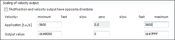
Now you set the velocity values that are sent to the actuator. For this purpose, you must know the maximum velocity in application units and the corresponding raw value of the transferred data. In this example, the maximum velocity is achieved by the output of the value 16#7FFF, which corresponds to a velocity of 10 rotations/s. This also corresponds to 3600 degrees/s according to the settings.
Mapping of variables to inputs and outputs
Map the variables with the axis data to the I/O modules. The available cyclical data of the axis are located in the data structures in and out. You can establish this connection in the device editor of the input and output device either programmatically or directly.
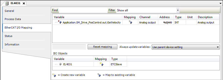
Connect the output (set speed) to the EL4031 device. Open the device in the editor and select the EtherCAT I/O mapping tab. Assign the out.iSetVelocity variable of the axis to the output. For a 32-bit output, out.diSetVelocity is used.
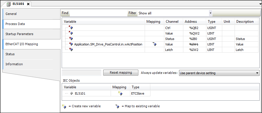
Proceed in the same way with the position input. Open the EL5101 device in the editor and set the position input value to in.wActPosition. For a 32-bit input, set the value to in.dwActPosition.
In order that the controller enable, quick stop, and limit switch operate, the corresponding inputs of SMC_PosControlInput must be defined by the values of the drive. The outputs of SMC_PosControlOutput must be transmitted to the drive (description, see below). If the drive does not support quick stop, for example, then SM_Drive_PosControl.in.bDriveStartRealState := TRUE must be set and SM_Drive_PosControl.out.bDriveStart can be ignored. In this example, bDriveStartRealState and bRegulatorRealState must be set in the application.
SM_Drive_PosControl.in.bDriveStartRealState := TRUE;
SM_Drive_PosControl.in.bRegulatorRealState := TRUE;
Determining the dead time of the system
Now set online mode with the axis and set the control parameters.
Notice
Please note that the axis may move out of control and therefore take corresponding safety precautions.
Then attempt to operate the axis without position control. fKp is already set to 0.0 and the scaling settings are verified. Switch the axis to MC_Power and start MC_MoveVelocity. The axis moves now with the programmed velocity of 1 U/s. In the case of deviations, you must correct the scaling accordingly.
End the movement, for example with MC_MoveRelative, and start the trace function.
Determine the dead time of the system by measuring the time offset between the set and actual position.
In MC_MoveRelative, set the maximum velocity and a large acceleration. Start the trace record with MC_MoveRelative. Now determine the time difference between the start movement of the set position and the first reaction of the actual position.
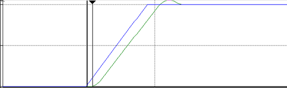
To determine the number of offset cycles, divide the time difference by the cycle time.
Now attempt to determine the correct setting for fKp. For this purpose, set fKp to a small number (e.g. 0.0001) and increase it in steps. Check the behavior for each change with the trace record. When you determine fluctuations, the upper limit is reached. Now reduce the value of fKp by approximately 10% and specify this value in the device configuration. Now you can use the axis.
Function block 'SMC_PosControlInput'
|
Name |
Data type |
Initial value |
Description |
|
bLimitPos |
BOOL |
Limit switch in positive direction (for finite axes only) To activate the monitoring, bHWLimitEnable must be TRUE. This is achieved typically by writing the corresponding parameter number 1206 by means of MC_WriteBoolParameter. |
|
|
bLimitNeg |
BOOL |
Limit switch in negative direction |
|
|
wActPosition |
WORD |
Current position (actual position) as 16-bit value |
|
|
dwActPosition |
DWORD |
Current position (actual position) as 32-bit value |
|
|
bExternalError |
BOOL |
External error |
|
|
bRegulatorRealState |
BOOL |
TRUE: Axis in control |
|
|
bDriveStartRealState |
BOOL |
FALSE: Axis in Quick Stop |
|
|
dwEncoderCounterModulo |
DWORD |
0 |
|
|
bDelayActivation |
BOOL |
TRUE: As long as bDelayActivation is TRUE, SM3_Drive_PosControl does not switch to communication state 100. Use case: The value is held at TRUE until the applied encoder yields valid positional values. |
Function block 'SMC_PosControlOutput'
Library: SM3_Drive_PosControl
|
Name |
Data type |
Initial value |
Description |
|
bRegulatorOnIn |
BOOL |
TRUE: The axis should be controlled. |
|
|
bDriveStart |
BOOL |
FALSE: The axis should execute a quick stop. |
|
|
diSetVelocity |
DINT |
Set velocity |
|
|
iSetVelocity |
INT |
Set velocity |