Controlling the Movement of Single Axes in CFC with a Visualization Template
Refer to the sample project PLCopenSingle2.project in the installation directory of CODESYS.
Any of the other IEC implementation languages can also be used instead of ST, for example CFC here. This language demonstrates the start and interrupt mechanism of the function blocks. In addition, the different start modes for the function block MC_MoveAbsolute can be tested for rotatory axes
Insert a virtual drive named Drive in the device tree below SoftMotion General Axis Pool.
Double-click the object to open its editor.
Change the parameters to a rotary drive with a period of 360°.
Axis type: Modulo
Modulo value [u]: 360.0
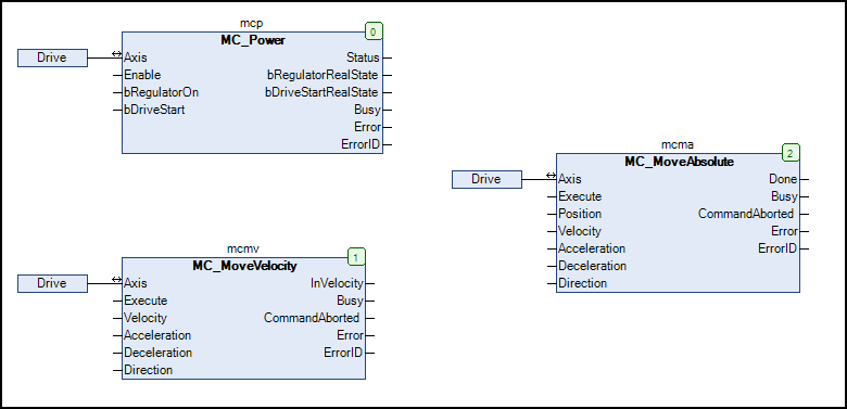
Create a MOTION_PRG program in CFC. Insert the function blocks MC_Power, MC_MoveAbsolute, and MC_MoveVelocity.
We recommend that you initialize the function block inputs. Then you do not have to specify the values again and again later when starting this test application.
PROGRAM MOTION_PRG
VAR
mcp: MC_Power := (Enable:=TRUE, bRegulatorOn:=TRUE, bDriveStart:=TRUE);
mcmv: MC_MoveVelocity :=(Velocity:=100, Acceleration:=100, Deceleration:=100, Direction:=positive);
mcma: MC_MoveAbsolute := (Position:=180, Velocity:=100, Acceleration:=100, Deceleration:=100, Direction:=positive);
END_VAR
Add the call of the MOTION_PRG program to the task MainTask.
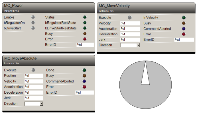
Add a Visualization object to the application.
Position the visualization templates VISU_NEW_MC_MoveAbsolute, VISU_NEW_MC_MoveVelocity, VISU_NEW_MC_Power, and RotDrive in the visualization editor. Link these to the function block instances of MOTION_PRG.
⇒ 
Compile the project and download it to the PLC. Start the project.
Open the visualization in the editor. Click the Enable input (MC_Power) and then the Execute input (MC_Move_Absolute).
⇒ The drive rotates.
Open the Drive virtual axis in the editor.
⇒ In the Online part of the General tab, you see the axis motion.
Experiment with the parameters of these function blocks. Change the parameters and observe the behavior.