Combining position and tool kinematics
With the axis group configurator, you can combine position kinematics and tool kinematics. As a result, a large number of robots can be configured with a small number of kinematics.
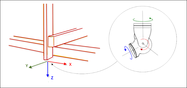
Examples of position kinematics include gantries (Kin_Gantry3) and tripods (Kin_Tripod_Lin, Kin_Tripod_Rotary). These kinematics can travel a point but not any number of orientations. The front coordinate system of a position kinematics is referred to as a flange coordinate system. It defines the place where tool kinematics are fixed (figure on left).
Examples of tool kinematics include Kin_CAxis, Kin_Wrist2, and Kin_Wrist3. These kinematics can effect a desired orientation of the TCP, but not reach any number of positions (figure on right).
By combining both types of kinematics, it is possible to travel any number of positions in the desired orientation.
Not every combination of position kinematics and tool kinematics is possible because sometimes the inverse transformation cannot be determined as unique. An example is a SCARA with two articulations as position kinematics and Kin_CAxis_Tool with a tool offset that is not zero in the X or Y coordinate. The orientation of the flange coordinate system of the SCARA is not constant. It is turned about the Z axis opposite the zero position. For the inverse transformation, this rotation is not known yet what the unique determination of the axis angle makes impossible in this case.
The possibility of a combination can first be checked in runtime mode because it depends on the parameterization of the kinematics. In this case, the error SMC_TRAFO_INVALID_COUPLING is displayed.
Behavior for programming "impossible" orientations
In practice, it is often useful when orientations can be programmed that are not reachable for the kinematics. As a simple example, we consider a SCARA robot with a tool with a degree of freedom (rotation on Z). In principle, this robot can only accept orientations for which the tool points straight down.
Given that positions should be traveled on a tool and the tool is easily tilted from the X/Y plane. Users teach this workpiece and program the positions and orientations relative to the workpiece. By tilting the workpiece, orientations result for which the tool direction is tilted easily from the perpendicular one.
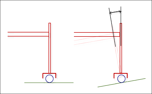
How do we deal with such an "impossible" and unreachable orientation? A drastic measure would be tor report a workspace violation. However, that would make programming tedious, as the example shows. Therefore, the tool kinematics (Kin_CAxis_Tool in the example) are implemented in such as way that they accept the next reachable orientation. In the example, this means the commanded orientation is tilted so that the tool is perpendicular and this orientation is then accepted.
The behavior can be reduced to the following rules (provided the position kinematics can position in all three spatial directions).
The position is always traveled exactly (otherwise an error is reported).
If not reachable, the orientation is projected on the next reachable position.
The tool direction has priority when projecting the orientation.
The difficulties discussed here occur because the tool kinematics do not have the three degrees of freedom to reach all desired orientations. This is the case for Kin_Wrist2 and Kin_CAxis, but not Kin_Wrist3.
Even more difficult is when the position kinematics also do not have all spatial degrees of freedom. (This does not happen often in practice.) An example is the combination of Kin_Gantry2, a gantry that can position in X/Y only, Kin_Wrist2, and a tool with only two degrees of freedom. In this case, there are impossible orientations and impossible positions because the Z coordinate is already determined by the tool length and the position of the orientation axis. Therefore, we recommend that you do not use these kinds of combinations, or in this case program only reachable positions.
Annotations for own created kinematics
Users who want to create their own position or orientation kinematics have to implement the following interfaces for their kinematics function blocks:
For position kinematics: The interface ISMPositionKinematics2 with the methods AxesToOrientation and GetOrientationImage. AxesToOrientation is an abbreviated forward transformation that calculates the orientation of the flange coordinate system from the axis values. It is necessary only for reasons of efficiency, for example, because nothing has to be calculated here for a gantry, but a constant orientation can be returned. GetOrientationImage returns how the orientation of the flange coordinate system can be modified. This method is necessary only for checking whether or not tool kinematics are compatible with the position kinematics.
For tool kinematics: The interface ISMToolKinematics2 with the methods GetPositionFromOrientation2 and IsCompatibleWithPosKin. GetPositionFromOrientation2 calculates the vector between the flange coordinate system and the TCP from the desired orientation (in the MCS). This calculation is necessary for the inverse transformation of the combined kinematics. The method IsCompatibleWithPosKin checks whether the tool kinematics are compatible with the position kinematics.
See also