Orientation Interpolation for CP Movements
For CP movements such as MC_MoveLinearAbsolute, MC_MoveLinearRelative, MC_MoveCircularAbsolute, or MC_MoveCircularRelative, any target orientation of the tool can be specified via the target position of the movement. The consequence is that the orientation of the tool is converted to the target orientation during the path movement, where the tip of the tool travels on the path. For the orientation interpolation, it does not make any difference in which coordinate system the target orientation was given, either in axis coordinates (ACS) or machine coordinates (MCS).
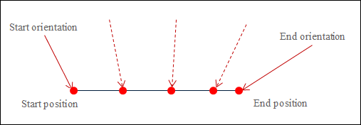
The following image shows a linear interpolation with the simultaneous orientation interpolation. The red arrow indicates the direction of the tool at the start and end points. The dashed red line indicates how the tool is positioned at some locations during interpolation.

The function blocks mentioned above for path movements have the OrientationMode input. This input defines how the start orientation is passed to the target orientation.
Great circle interpolation (SMC_Orientation_Mode.GreatCircle).
This setting is set by default. The start orientation is also passed to the target orientation in the shortest distance. The shortest distance means that the tool is rotated in the target orientation so that the traveled angle of the rotation is minimized.
Axis orientation interpolation (SMC_Orientation_Mode.Axis).
Example 1: Great circle interpolation
We observe a gantry with a C-axis with a value range of -360° to 360°. The start orientation is C=179°, and the target orientation is C=-175°. The great circle interpolation moves the C-axis of the ZYZ Euler angle (A,B,C) proportionally to the traveled distance on the path from 179° in the positive direction past 180° to 185°, which corresponds to -175°. At this time, it also travels a total angle of 6°.
Example 2: Axis orientation interpolation
Again we observe the gantry with a C-axis with a value range of -180° to 180°. The start orientation is C=179°, and the target orientation is C=-175°. The axis interpolation moves the C-axis of the gantry proportionally to the traveled distance on the path from 179° in the negative direction past 0° to -175°, traveling a total angle of 354°. (If the great circle interpolation was used in this example, then an error would have occurred, because the working space of the C axis would have been exceeded.)
These two types of interpolation differentiate in some important characteristics.
In great circle interpolation, the change in the orientation of the tool can be predicted. In axis interpolation, it is difficult to predict the change in orientation, because the orientation axes can affect the orientation differently depending on the position. The axis orientation interpolation shares this characteristic with PTP movements. (However, this does not mean that it is difficult to predict the path in space for axis orientation interpolation. The path is the same for both types of orientation interpolation, and the TCP always travels the defined contour exactly.)
With great circle interpolation, singularities in the tool kinematics cannot be traveled. This is easily possible with axis interpolation.
In great circle interpolation, violations to the axis limits of the orientation axes can result, as mentioned in Example 2. When commanding, it is also required to make sure that no axis limits are violated when the target orientation is traveled with the shortest rotation.
With axis interpolation, it is possible to rotate more than 360°. If an orientation axis has a working space of more than 360°, then you can travel to position 540°, for example, instead of to position 180°. This corresponds to the same orientation of the tool. With great circle interpolation, this is not possible. The shortest rotation to the target orientation always corresponds to a total angle of 180° at most.
The axis interpolation is not supported by all kinematics. The kinematics documentation contains more information about this.
The axis interpolation is not supported for tracking movements (dynamic PCS).
See also
Singularities in axis orientation interpolation
With axis orientation interpolation, a path movement can take place by the singularities of the tool kinematics, which can make the programming significantly easier. The singularities of the positioning kinematics change for this purpose.
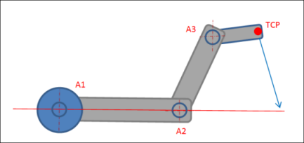
For large circular interpolation, Scara3_Z has a singularity if the flange point (A3) lies on the line defined by the first arm part (if the second joint angle is 0°).
For axis orientation interpolation, the singularities of the positioning kinematics change so that the TCP takes on the role that the flange point (A3) has otherwise. This happens when the TCP (not the flange point) lies on the line defined by the first arm part. When commanding a movement with axis orientation interpolation, it is checked whether or not this changed singularity lies between the start and target positions of the movement. If so, then the movement is not accepted and an error is issued.

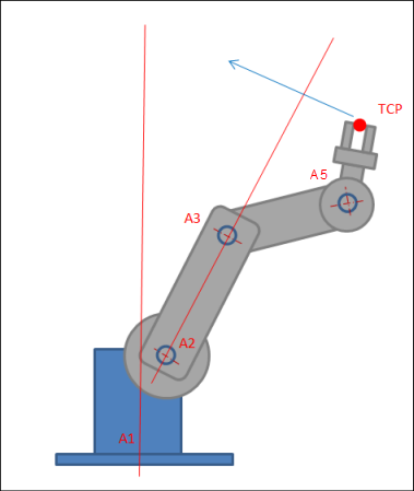
For 6-axis articulated arm robots, the situation is comparable to Scara3_Z, but two singularities are possible. The first occurs when the TCP lies on the line through A2 and A3. The second occurs when the TCP lies on the line through A1. Even here when The commanding also checks here that no singularity is traveled through.

Note
It can happen that the configuration of Scara3 (or the 6-axis articulated arm robot) changes when traveling with axis orientation interpolation. However, at the end of the movement the same configuration is always applied that the robot had at the starting point.