Parts Identification and Functions
Parts Identification and Functions
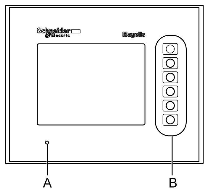
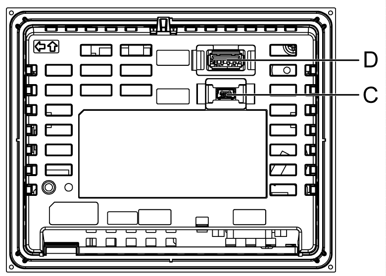
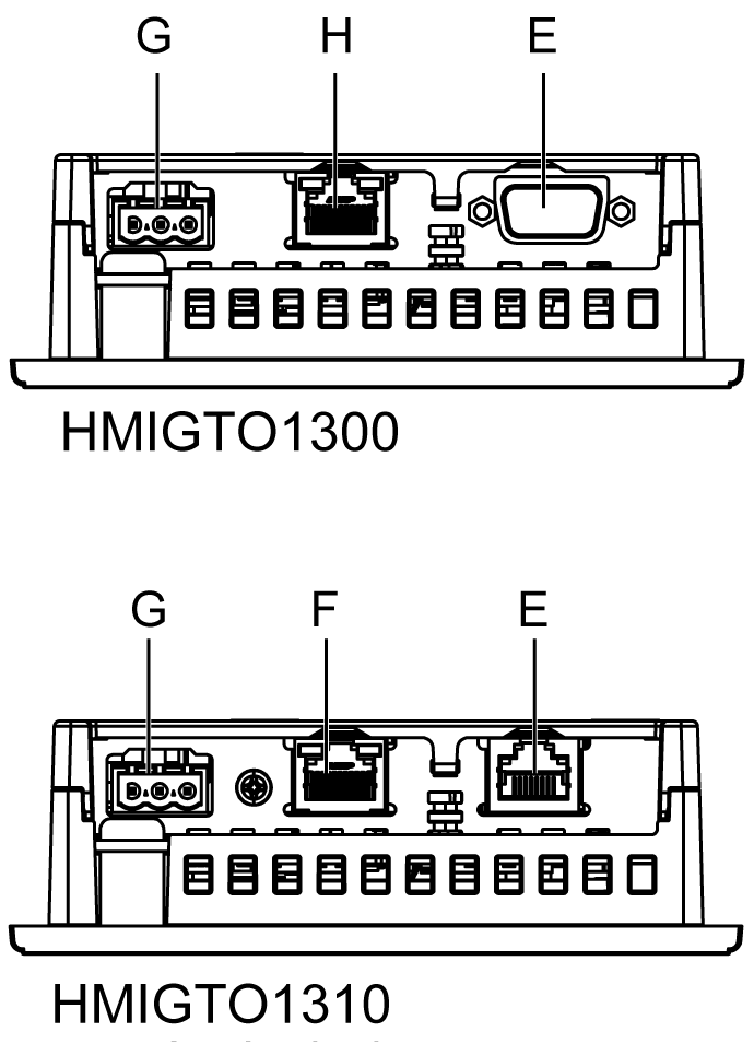
HMIGTO1300/1310 Parts Identification
|
Side |
HMIGTO1300/1310 |
|---|---|
|
Front |
|
|
Rear |
|
|
Bottom |
|
|
Part |
Name |
Description |
|---|---|---|
|
A |
Status LED |
*1 |
|
B |
Function Switches |
Six switches (F1 to F6). You can define operations for these switches using Vijeo Designer. |
|
C |
USB (mini-B) Interface |
Conforms to USB2.0 (mini-B) x 1. Communication Distance: 5 m (16.4 ft) or less. |
|
D |
USB (Type A) Interface |
Conforms to USB2.0 (Type A) x 1. Power supply voltage: 5 Vdc+/-5%. Output Current: 500 mA or less. Maximum communication distance: 5 m (16.4 ft). |
|
E |
Serial Interface (COM1) |
HMIGTO1300: RS-232C Serial Interface. Connector: D-Sub 9 pin (plug) x 1. HMIGTO1310: RS-232C/485 Serial Interface. (You can switch the communication method via software.) Connector: Modular jack (RJ45). |
|
F |
Ethernet Interface*2 |
Ethernet transmission interface (10BASE-T/100BASE-TX) Connector: Modular jack (RJ45) x 1. Ethernet Interface is not attached to HMIGTO1300. |
|
G |
Power Plug Connector |
- |
|
H |
Serial Interface (COM2) |
HMIGTO1300: RS-485 Serial Interface. Connector: Modular jack (RJ45) x 1. |
*1 Status LED operations are as shown below:
|
Color |
Indicator |
Description |
|---|---|---|
|
Green |
ON |
In operation |
|
Orange |
Flashing |
Software starting up. |
|
Red |
ON |
Power is turned ON. |
|
- |
OFF |
Power is turned OFF. |
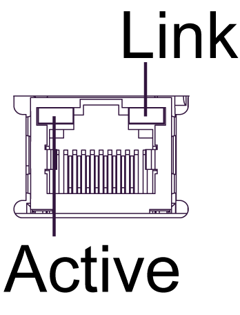
*2 Ethernet LED operations are as shown below.
|
|
Color |
Indicator |
Description |
|---|---|---|---|
|
Green (Active) |
Flashing |
Data transmission is occurring. |
|
OFF |
No data transmission. |
||
|
Green (Link) |
ON |
Data transmission is available in 10BASE-T/100BASE-TX. |
|
|
OFF |
No connection or subsequent transmission failure. |
HMIGTO2300/2310/2315 Parts Identification
|
Side |
HMIGTO2300 / HMIGTO2310 |
HMIGTO2315 |
|---|---|---|
|
Front |
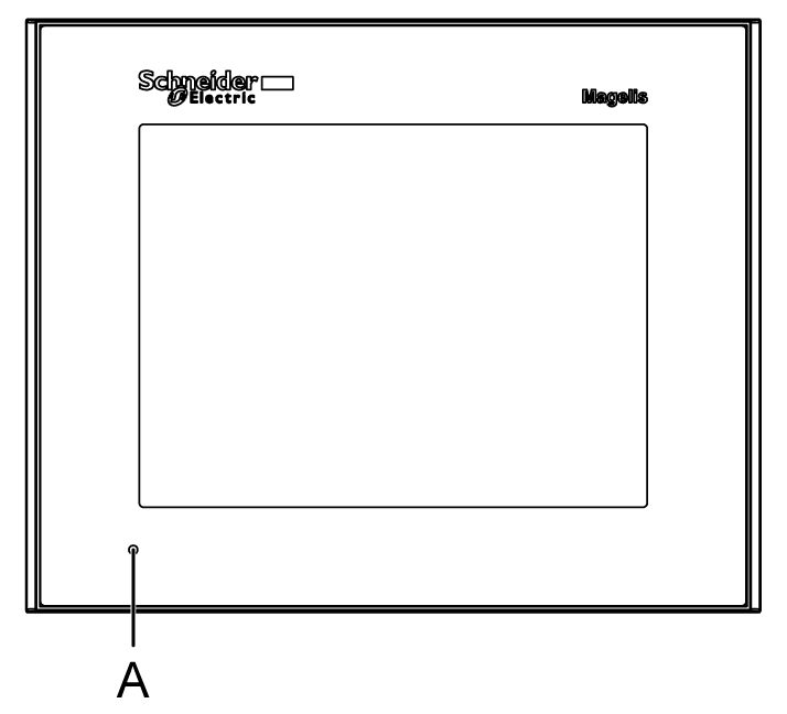
|
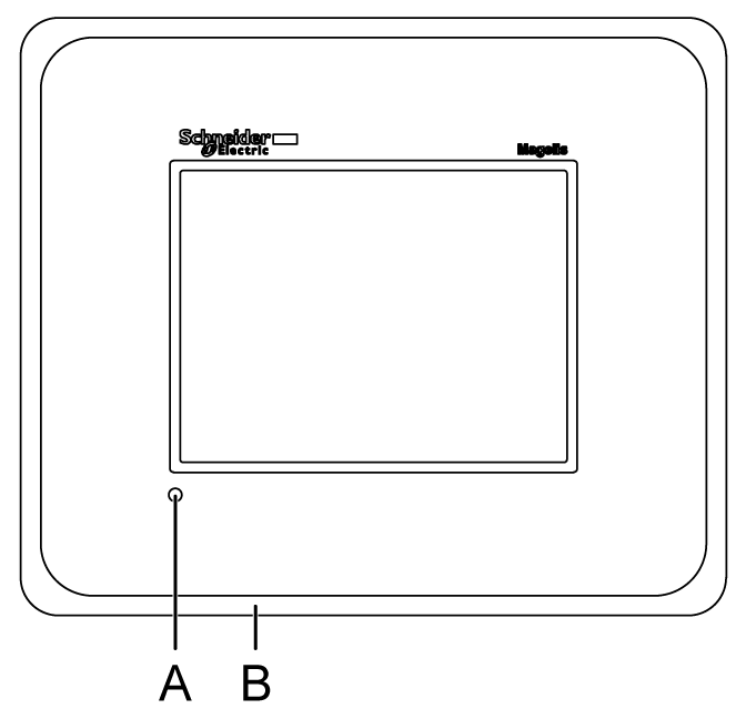
|
|
Right |
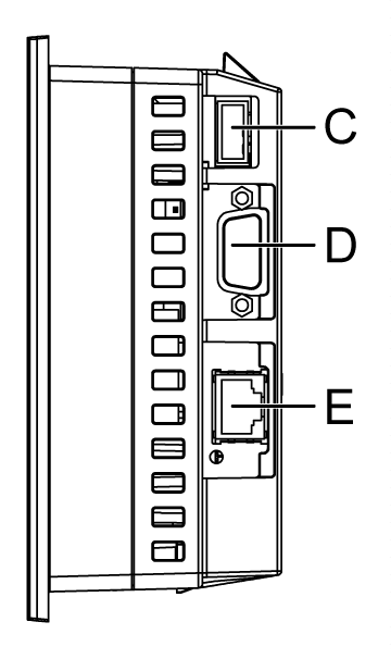
|
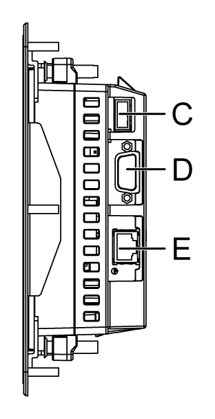
|
|
Rear |
|
|
|
Bottom |
|
|
|
Part |
Name |
Description |
|---|---|---|
|
A |
Status LED |
*1 |
|
B |
Stainless Steel Bezel (grade 304) |
HMIGTO2315 only. |
|
C |
USB (Type A) Interface |
Conforms to USB2.0 (Type A) x 1. Power supply voltage: 5 Vdc+/-5%. Output Current: 500 mA or less. Maximum communication distance: 5 m (16.4 ft). |
|
D |
Serial Interface (COM1) |
RS-232C Serial Interface. Connector: D-Sub 9 pin (plug) x 1. |
|
E |
Serial Interface (COM2)*2 |
RS-485 Serial Interface. Connector: Modular jack (RJ45). |
|
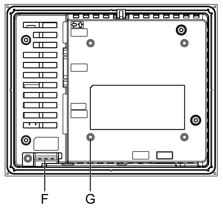
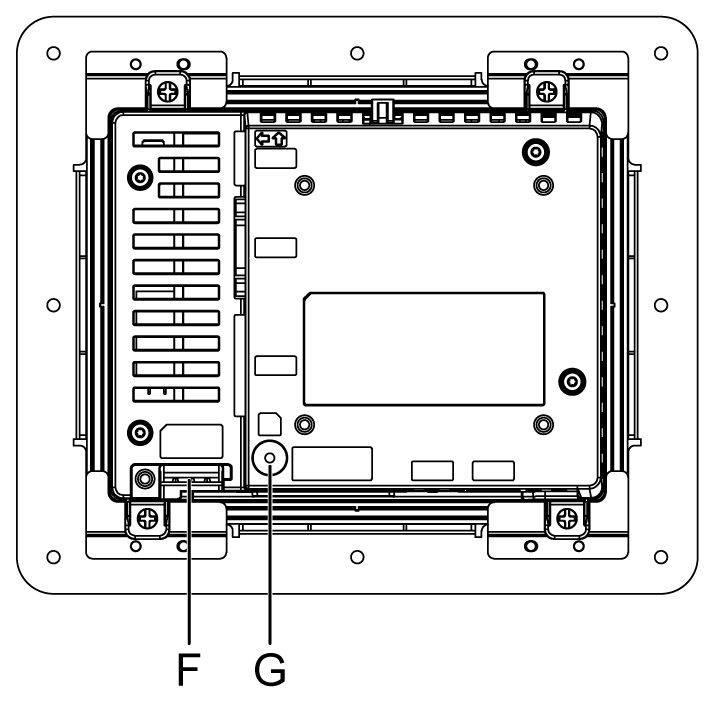
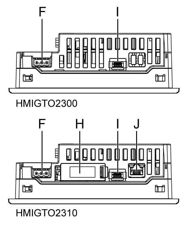
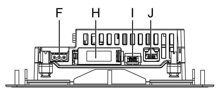
F |
Power Plug Connector |
- |
|
G |
SD Card Access LED*3 |
This lamp lights up when SD card is inserted. For more information, refer to SD Card Insertion/Removal. NOTE: SD card access LED is not available on HMIGTO2300. |
|
H |
SD Card Interface Cover/Replacement Battery Insertion Cover |
For information on how to open the cover, and insert or remove the SD card, refer to SD Card Insertion/Removal. For information on how to open the cover and replace the battery, refer to Replacing the Primary Battery. NOTE: This cover is not on HMIGTO2300. |
|
I |
USB (mini-B) Interface |
Conforms to USB2.0 (mini-B) x 1. Communication Distance: 5 m (16.4 ft) or less. |
|
J |
Ethernet Interface*4 |
Ethernet transmission interface (10BASE-T/100BASE-TX) Connector: Modular jack (RJ45) x 1. NOTE: Ethernet Interface is not available on HMIGTO2300. |
*1 Status LED operations are as shown below:
|
Color |
Indicator |
Description |
|---|---|---|
|
Green |
ON |
In operation |
|
Orange |
Flashing |
Software starting up. |
|
Red |
ON |
Power is turned ON. |
|
- |
OFF |
Power is turned OFF. |
*2 COM2 LED operations are as shown below.
|
Color |
Indicator |
Description |
|---|---|---|
|
Yellow |
ON |
Communication (sending or receiving data) is occurring. |
|
OFF |
No communication. |
*3 SD card access LED operations are as shown below.
|
Color |
Indicator |
Description |
|---|---|---|
|
Green (Active) |
ON |
The SD card is inserted. |
|
OFF |
The SD card is not inserted or is not being accessed. |
*4 Ethernet LED operations are as shown below.
|
|
Color |
Indicator |
Description |
|---|---|---|---|

|
Green (Active) |
Flashing |
Data transmission is occurring. |
|
OFF |
No data transmission. |
||
|
Green (Link) |
ON |
Data transmission is available in 10BASE-T/100BASE-TX. |
|
|
OFF |
No connection or subsequent transmission failure. |
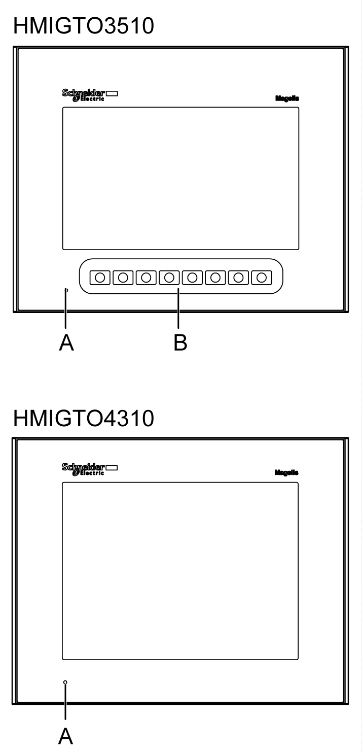
HMIGTO3510/4310 Parts Identification
|
Side |
HMIGTO3510/4310 |
|---|---|
|
Front |
|
|
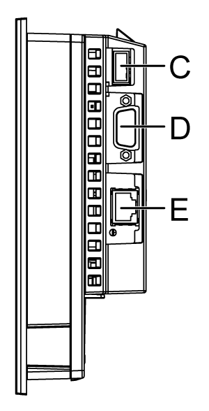
Right |
|
|
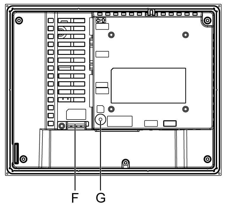
Rear |
|
|
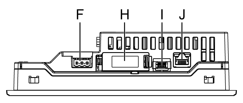
Bottom |
|
|
Part |
Name |
Description |
|---|---|---|
|
A |
Status LED |
*1 |
|
B |
Function Switches |
Height switches (F1 to F8). You can define operations for these switches using Vijeo Designer. |
|
C |
USB (Type A) Interface |
Conforms to USB2.0 (Type A) x 1. Power supply voltage: 5 Vdc+/-5%. Output Current: 500 mA or less. Maximum communication distance: 5 m (16.4 ft). |
|
D |
Serial Interface (COM1) |
RS-232C Serial Interface. Connector: D-Sub 9 pin (plug) x 1. |
|
E |
Serial Interface (COM2)*2 |
RS-485 Serial Interface. Connector: Modular jack (RJ45) x 1. |
|
F |
Power Plug Connector |
- |
|
G |
SD Card Access LED*3 |
This lamp lights up when SD card is inserted. For more information, refer to SD Card Insertion/Removal. |
|
H |
SD Card Interface Cover/Replacement Battery Insertion Cover |
For information on how to open the cover, and insert or remove the SD card, refer to SD Card Insertion/Removal. For information on how to open the cover and replace the battery, refer to Replacing the Primary Battery. |
|
I |
USB (mini-B) Interface |
Conforms to USB2.0 (mini-B) x 1. Communication Distance: 5 m (16.4 ft) or less. |
|
J |
Ethernet Interface*4 |
Ethernet transmission interface (10BASE-T/100BASE-TX) Connector: Modular jack (RJ45) x 1. |
*1 Status LED operations are as shown below:
|
Color |
Indicator |
Description |
|---|---|---|
|
Green |
ON |
In operation |
|
Orange |
Flashing |
Software starting up. |
|
Red |
ON |
Power is turned ON. |
|
- |
OFF |
Power is turned OFF. |
*2 COM2 LED operations are as shown below.
|
Color |
Indicator |
Description |
|---|---|---|
|
Yellow |
ON |
Communication (sending or receiving data) is occurring. |
|
OFF |
No communication. |
*3 SD card Access LED operations are as shown below.
|
Color |
Indicator |
Description |
|---|---|---|
|
Green (Active) |
ON |
The SD card is inserted. |
|
OFF |
The SD card is not inserted or is not being accessed. |
*4 Ethernet LED operations are as shown below.
|
|
Color |
Indicator |
Description |
|---|---|---|---|

|
Green (Active) |
Flashing |
Data transmission is occurring. |
|
OFF |
No data transmission. |
||
|
Green (Link) |
ON |
Data transmission is available in 10BASE-T/100BASE-TX. |
|
|
OFF |
No connection or subsequent transmission failure. |
HMIGTO5310/5315 Parts Identification
|
Side |
HMIGTO5310 |
HMIGTO5315 |
|---|---|---|
|
Front |
|
|
|
Rear |
|
|
|
Bottom |

|

|
|
Part |
Name |
Description |
|---|---|---|
|
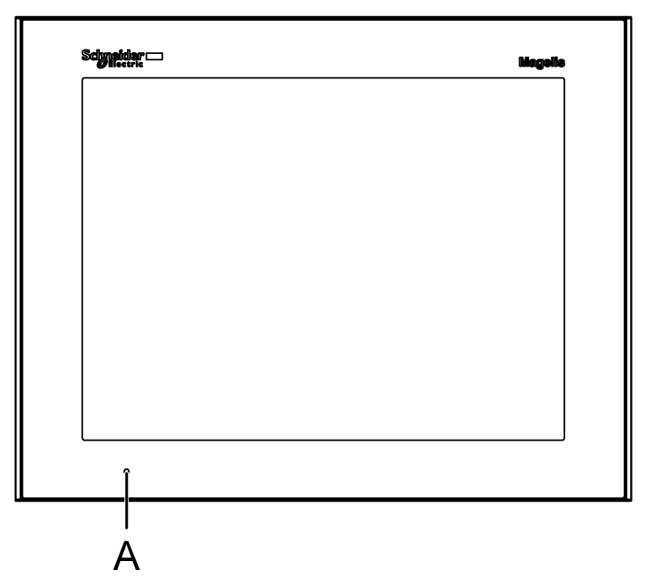
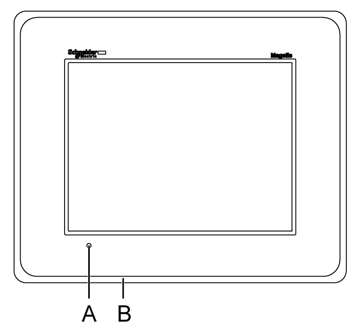
A |
Status LED |
*1 |
|
B |
Stainless Steel Bezel (grade 304) |
HMIGTO5315 only. |
|
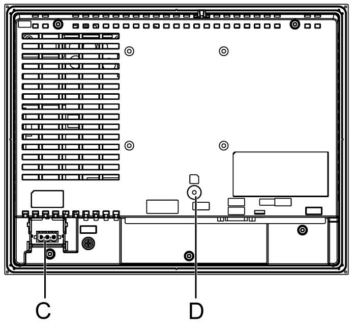
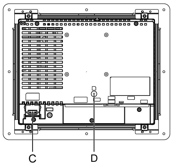
C |
Power Plug Connector (DC model) |
- |
|
D |
SD Card Access LED*2 |
This lamp lights up when SD card is inserted. NOTE: Do not remove or insert the SD card when the LED lamp is on. Doing so may damage data on the SD card. |
|
E |
Ethernet Interface*3 |
Ethernet transmission interface (10BASE-T/100BASE-TX) Connector: Modular jack (RJ45) x 1. |
|
F |
USB (mini-B) Interface |
Conforms to USB2.0 (mini-B) x 1. Communication Distance: 5 m (16.4 ft) or less. |
|
G |
SD Card Interface Cover/Replacement Battery Insertion Cover |
For information on how to open the cover, and insert or remove the SD card, refer to SD Card Insertion/Removal. For information on how to open the cover and replace the battery, refer to Replacing the Primary Battery. |
|
H |
Serial Interface (COM2)*4 |
RS-485 Serial Interface. Connector: Modular jack (RJ45). |
|
I |
Serial Interface (COM1) |
RS-232C Serial Interface. Connector: D-Sub 9 pin (plug) x 1. |
|
J |
USB (Type A) Interface |
Conforms to USB2.0 (Type A) x 1. Power supply voltage: 5 Vdc+/-5%. Output Current: 500 mA or less. Maximum communication distance: 5 m (16.4 ft). |
*1 Status LED operations are as shown below:
|
Color |
Indicator |
Description |
|---|---|---|
|
Green |
ON |
In operation |
|
Orange |
Flashing |
Software starting up. |
|
Red |
ON |
Power is turned ON. |
|
- |
OFF |
Power is turned OFF. |
*2 SD card access LED operations are as shown below.
|
Color |
Indicator |
Description |
|---|---|---|
|
Green (Active) |
ON |
The SD card is inserted. |
|
OFF |
The SD card is not inserted or is not being accessed. |
*3 Ethernet LED operations are as shown below.
|
|
Color |
Indicator |
Description |
|---|---|---|---|

|
Green (Active) |
Flashing |
Data transmission is occurring. |
|
OFF |
No data transmission. |
||
|
Green (Link) |
ON |
Data transmission is available in 10BASE-T/100BASE-TX. |
|
|
OFF |
No connection or subsequent transmission failure. |
*4 COM2 LED operations are as shown below.
|
Color |
Indicator |
Description |
|---|---|---|
|
Yellow |
ON |
Communication (sending or receiving data) is occurring. |
|
OFF |
No communication. |
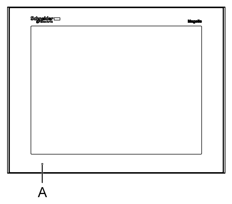
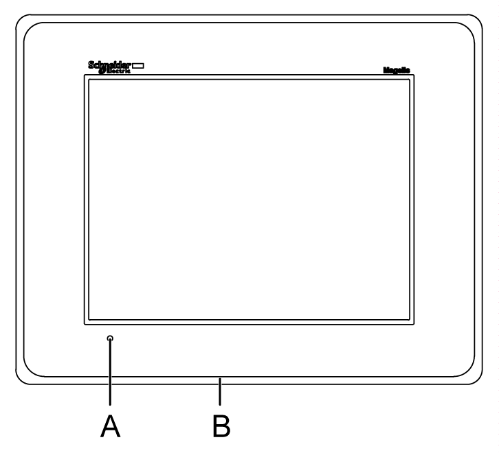
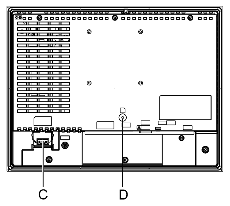
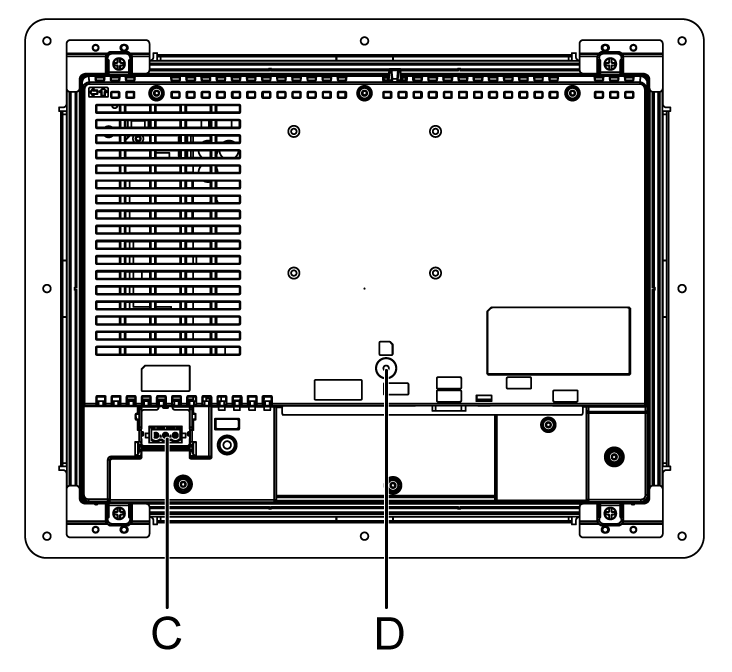
HMIGTO6310/6315 Parts Identification
|
Side |
HMIGTO6310 |
HMIGTO6315 |
|---|---|---|
|
Front |
|
|
|
Rear |
|
|
|
Bottom |

|

|
|
Part |
Name |
Description |
|---|---|---|
|
A |
Status LED |
*1 |
|
B |
Stainless Steel Bezel (grade 304) |
HMIGTO6315 only. |
|
C |
Power Plug Connector (DC model) |
- |
|
D |
SD Card Access LED*2 |
This lamp lights up when SD card is inserted. NOTE: Do not remove or insert the SD card when the LED lamp is on. Doing so may damage data on the SD card. |
|
E |
Ethernet Interface*3 |
Ethernet transmission interface (10BASE-T/100BASE-TX) Connector: Modular jack (RJ45) x 1. |
|
F |
USB (mini-B) Interface |
Conforms to USB2.0 (mini-B) x 1. Communication Distance: 5 m (16.4 ft) or less. |
|
G |
SD Card Interface Cover/Replacement Battery Insertion Cover |
For information on how to open the cover, and insert or remove the SD card, refer to SD Card Insertion/Removal. For information on how to open the cover and replace the battery, refer to Replacing the Primary Battery. |
|
H |
Serial Interface (COM2)*4 |
RS-485 Serial Interface. Connector: Modular jack (RJ45) |
|
I |
Serial Interface (COM1) |
RS-232C Serial Interface. Connector: D-Sub 9 pin (plug) x 1. |
|
J |
USB (Type A) Interface |
Conforms to USB2.0 (Type A) x 1. Power supply voltage: 5 Vdc+/-5%. Output Current: 500 mA or less. Maximum communication distance: 5 m (16.4 ft). |
*1 Status LED operations are as shown below:
|
Color |
Indicator |
Description |
|---|---|---|
|
Green |
ON |
In operation |
|
Orange |
Flashing |
Software starting up. |
|
Red |
ON |
Power is turned ON. |
|
- |
OFF |
Power is turned OFF. |
*2 SD card access LED operations are as shown below.
|
Color |
Indicator |
Description |
|---|---|---|
|
Green (Active) |
ON |
The SD card is inserted. |
|
OFF |
The SD card is not inserted or is not being accessed. |
*3 Ethernet LED operations are as shown below.
|
|
Color |
Indicator |
Description |
|---|---|---|---|

|
Green (Active) |
Flashing |
Data transmission is occurring. |
|
OFF |
No data transmission. |
||
|
Green (Link) |
ON |
Data transmission is available in 10BASE-T/100BASE-TX. |
|
|
OFF |
No connection or subsequent transmission failure. |
*4 COM2 LED operations are as shown below.
|
Color |
Indicator |
Description |
|---|---|---|
|
Yellow |
ON |
Communication (sending or receiving data) is occurring. |
|
OFF |
No communication. |