This product is designed for use on flat surfaces of Type 1, Type 4X (Indoor Use Only) or Type 13 Enclosure.
Mount this product in an enclosure that provides a clean, dry, robust and controlled environment (IP66F, IP67F, Type 1, Type 4X [Indoor Use Only], or Type 13 Enclosure).
For Advanced Display, the front surface is IP66F, IP67F, Type 1, Type 4X (Indoor Use Only) or Type 13 Enclosure.
For Smart Display, the front surface is IP66F, IP67F, Type 1, Type 4X (Indoor Use Only) or Type 13 Enclosure.
|
Display Front Surface |
Enclosure Front Surface |
|
|---|---|---|
|
Smart Display |
Advanced Display |
|
|
IP66F, IP67F, Type 1, Type 4X (Indoor Use Only), Type 13 |
IP66F, IP67F, Type 1, Type 4X (Indoor Use Only), Type 13 |
IP66F, IP67F, Type 1, Type 4X (Indoor Use Only), Type 13 |
When the front USB cover*1 is open, the front surface is Type 1 Enclosure.
Be aware of the following when building this product into an end-use product:
oThe rear face of this product is not approved as an enclosure. When building this product into an end-use product, be sure to use an enclosure that satisfies standards as the end-use product’s overall enclosure.
oInstall this product in an enclosure with mechanical rigidity.
oThis product is not designed for outdoor use. UL certification obtained is for indoor use only.
oInstall and operate this product with its front panel facing outward.
*1 The necessary torque is 0.5 N•m (4.4 lb-in).
NOTE: IP66F and IP67F are not part of the UL certification.
|
|
|
RISK OF BURNING INJURY |
|
Failure to follow these instructions can result in injury or equipment damage. |
|
Check that the installation wall or cabinet surface is flat, in good condition and has no jagged edges. Metal reinforcing strips may be attached to the inside of the wall, near the panel-cut, to increase its rigidity. |
|
Decide on the thickness of the enclosure wall, based on the level of strength required: 1.6...5 mm (0.06...0.2 in). Even if the installation wall thickness is within the recommended range for the Panel Cut Dimensions, depending on wall’s material, size, and installation location of this product and other devices, the installation wall could warp. To prevent warping, the installation surface may need to be strengthened. |
|
Check that the ambient air temperature and the ambient humidity are within their specified ranges. When installing this product in a cabinet or enclosure, the ambient air temperature is the cabinet’s or enclosure’s internal temperature. 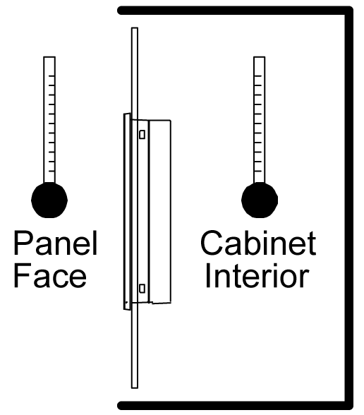
|
|
Be sure that heat from surrounding equipment does not cause this product to exceed its standard operating temperature. |
|
When mounting this product vertically, ensure that the right side of this product faces up. In other words, the DC power connector should be at the top. NOTE: For vertical mounting, make sure your screen editing software supports the function. 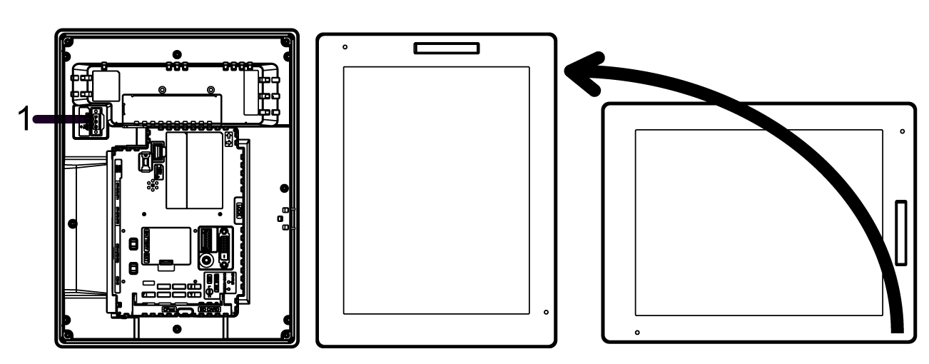
1 Power connector |
|
When installing this product in a slanted position, the product face should not incline more than 30°. 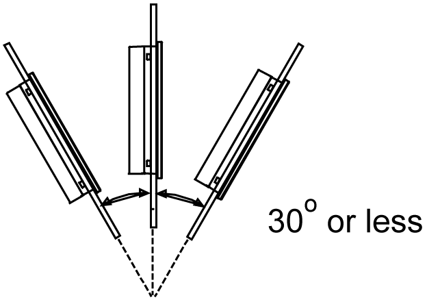
|
|
When installing this product in a slanted position with an incline more than 30°, the ambient temperature must not exceed 40 °C (104 °F). You may need to use forced air cooling (fan, A/C) to ensure the ambient operating temperature is 40 °C or less (104 °F or less). |
|
For easier maintenance, operation and improved ventilation, install this product at least 100 mm (3.94 in) away from adjacent structures and other equipment as shown in the following illustration: 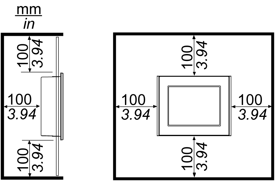
Please ensure you have enough space to insert and remove the storage card. |
|
For Wireless LAN models, do not block the wireless LAN antenna area with your hand, body or other objects. It may cause interference in wireless LAN communications. |
|
|
|
ELECTROMAGNETIC/RADIO INTERFERENCE |
|
If you are uncertain of the policy that applies to the use of the Wireless LAN model, ask the administrator about its use before you turn it on. |
|
Failure to follow these instructions can result in death, serious injury, or equipment damage. |
2.4 GHz Wireless Devices
The Wireless LAN model uses the 2.4 GHz frequency range, which is used by a wide range of wireless equipment. Example usage includes industrial, scientific, and medical equipment such as microwave ovens, on-site wireless stations (requiring licenses), low-power wireless stations (not requiring licenses) as well as amateur wireless stations (requiring licenses).
1 Before use, confirm that no on-site wireless stations and specified low-power wireless stations or amateur wireless stations operate in your vicinity.
2 In the event that the Wireless LAN model causes harmful interference to any other "on-site wireless stations", immediately change the channel frequency of the Wireless LAN model, or change its location, or halt operation of radio emissions and contact the administrator of the wireless network to resolve the issue.
Security on Your Wireless LAN
Because wireless LANs do not normally provide adequate data security, the following problems may occur.
1.Unlawful access of communication information.
oThere is a chance that information found in emails, and personal information such as user IDs, passwords, and credit card numbers, may be intentionally intercepted by a malicious third party.
2.Illegal Access
A malicious third party may be able to access personal or company data over the company's local area network without permission, to:
oObtain personal and confidential information (information leak)
oImpersonate someone by communicating as that person and disseminating invalid information (spoofing)
oAlter intercepted communications and re-transmitting tolerated content (falsification)
oCause critical damage to data and or systems due to a computer virus (damage).
This wireless LAN product includes security features that enable you to configure security-related settings that reduce the likelihood of the above-mentioned problems.
We recommend that you make yourself fully acquainted with the possible implications of what might happen if you use a wireless product without enabling security features, and that you configure security-related settings and use wireless products at your own responsibility.
Based on the panel cut dimensions, open a mount hole on the panel.
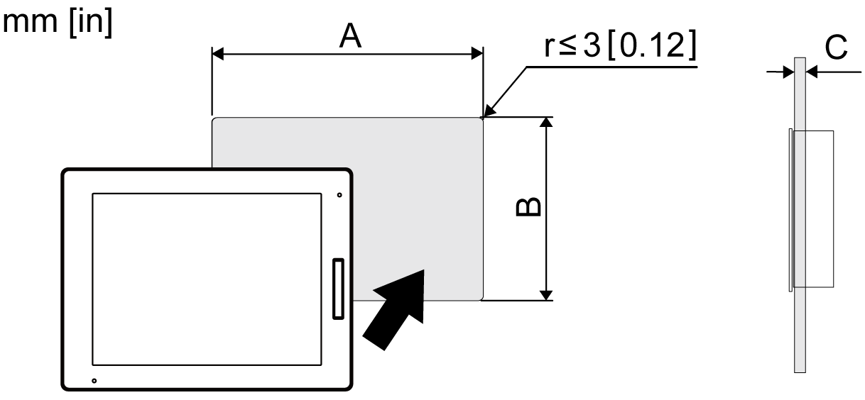
|
Model Name |
A |
B |
C |
|---|---|---|---|
|
HMIDT542 |
259 mm (+1/-0 mm) (10.2 in [+0.04/-0 in]) |
201 mm (+1/-0 mm) (7.91 in [+0.04/-0 in]) |
1.6...5 mm (0.06...0.2 in) |
|
HMIDT642 HMIDT643 |
301.5 mm (+1/-0 mm) (11.87 in [+0.04/-0 in]) |
227.5 mm (+1/-0 mm) (8.96 in [+0.04/-0 in]) |
|
|
HMIDT732 |
383.5 mm (+1/-0 mm) (15.1 in [+0.04/-0 in]) |
282.5 mm (+1/-0 mm) (11.12 in [+0.04/-0 in]) |
|
|
HMIDT752 |
396 mm (+1/-0 mm) (15.59 in [+0.04/-0 in]) |
277 mm (+1/-0 mm) (10.91 in [+0.04/-0 in]) |
|
|
HMIDT952 |
465 mm (+1/-0 mm) (18.31 in [+0.04/-0 in]) |
319 mm (+1/-0 mm) (12.56 in [+0.04/-0 in]) |
|
|
HMIDT351 |
190 mm (+1/-0 mm) (7.48 in [+0.04/-0 in]) |
135 mm (+1/-0 mm) (5.31 in [+0.04/-0 in]) |
|
|
HMIDT551 |
255 mm (+1/-0 mm) (10.04 in [+0.04/-0 in]) |
185 mm (+1/-0 mm) (7.28 in [+0.04/-0 in]) |
|
|
HMIDT651 |
295 mm (+1/-0 mm) (11.61 in [+0.04/-0 in]) |
217 mm (+1/-0 mm) (8.54 in [+0.04/-0 in]) |
Installing onto Display Module
|
NOTICE |
|
EQUIPMENT DAMAGE |
|
oWhen mounting this product vertically, install the Box Module onto the Display Module before attaching the Display Module to the panel. oWhen installing the Box Module onto the Display Module, place the Display Module on a clean and level surface with the screen facing downward. oAllow only qualified personnel to change the primary battery. |
|
Failure to follow these instructions can result in equipment damage. |
|
Step |
Action |
|---|---|
|
1 |
Pull the LOCK forward on the top of the Box Module to release the lock as illustrated. 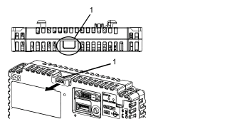
1 LOCK |
|
2 |
Insert the protruding points on the bottom left and right of the Box Module into the two holes on the back of the Display Module to attach the Box Module. 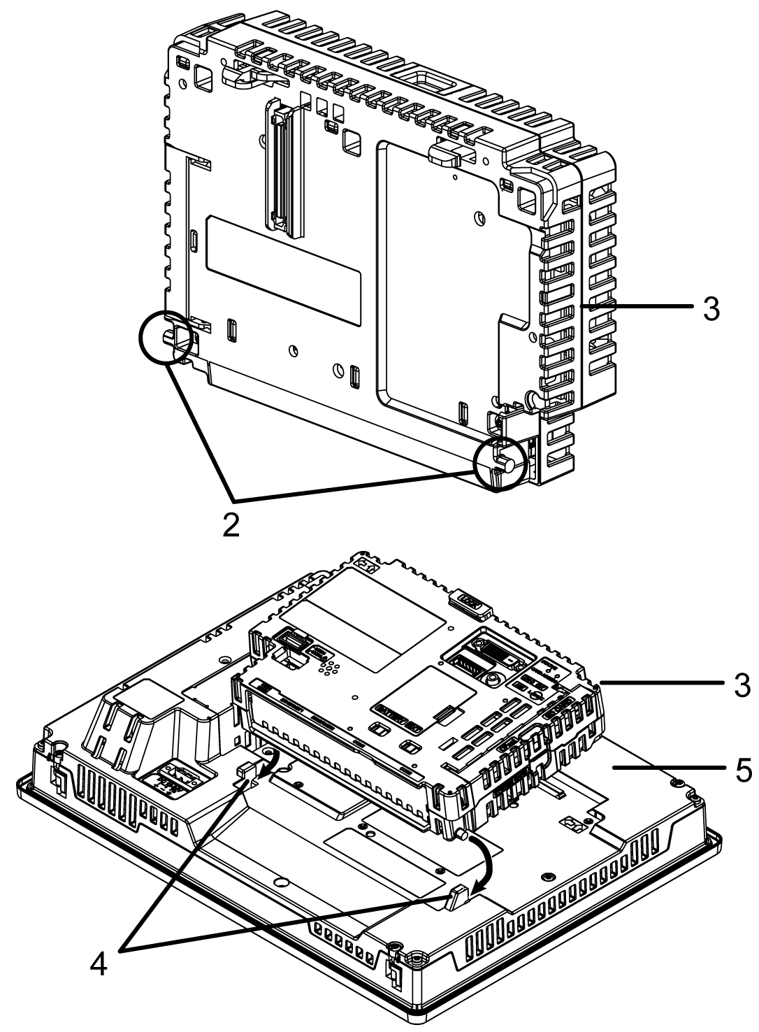
2 Protruding points 3 Box Module 4 Holes for insertion 5 Display Module |
|
3 |
Fully push on the LOCK on the top of the Box Module to mount the Box Module on the Display Module. 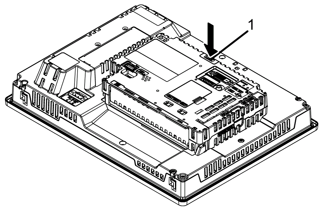
1 LOCK |
NOTE: For instructions on how to mount the Display Module to the panel, refer to Installing to the Panel.
|
NOTICE |
|
EQUIPMENT DAMAGE |
|
When this product is mounted vertically, first remove the Display Module from the panel, then remove the Box Module from the Display Module. |
|
Failure to follow these instructions can result in equipment damage. |
|
Step |
Action |
|---|---|
|
1 |
When mounting this product vertically, remove the Display Module from the panel and place the Display Module on a clean and level surface with the screen facing down. |
|
2 |
Release the LOCK on the top of the Box Module as illustrated. 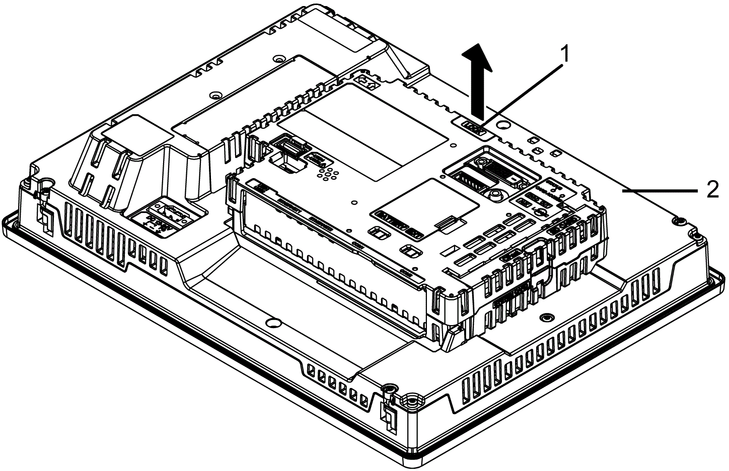
1 LOCK 2 Display Module |
|
3 |
Lift the Box Module in the direction indicated by arrow (A) in the diagram and remove it by sliding in the direction indicated by arrow (B). 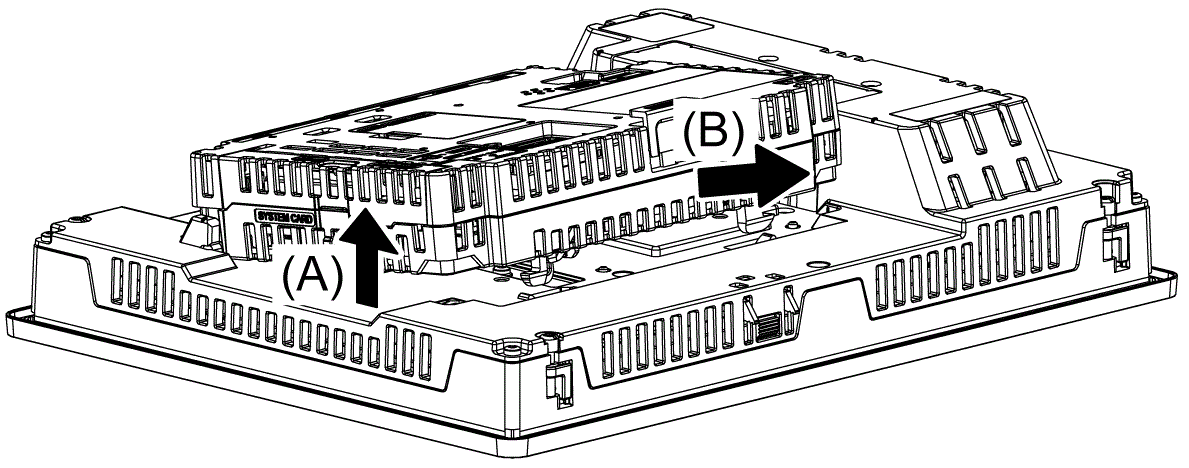
|
|
NOTICE |
|
EQUIPMENT DAMAGE |
|
oWhen mounting this product vertically, install the Box Module onto the Display Module before attaching the Display Module to the panel. oKeep this product stabilized in the panel-cut while you are installing or removing the screw fasteners. |
|
Failure to follow these instructions can result in equipment damage. |
|
Step |
Action |
|---|---|
|
1 |
When mounting this product vertically, place the Display Module on a clean and level surface with the screen facing down and mount the Box Module to the Display Module. |
|
2 |
Check that the Display Module’s gasket is seated securely into the bezel’s groove, which runs around the perimeter of the display panel frame. NOTE: Always use the installation gasket, since it absorbs vibration in addition to repelling water. For the procedure on replacing the installation gasket, refer to Replacing the Installation Gasket. |
|
3 |
Based on the Display Module's panel cut dimensions, open a mount-hole on the panel and attach the Display Module to the panel from the front side. 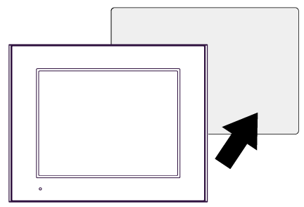
|
|
4 |
Confirm that the anti-drop lock on the top of the Display Module is attached to the panel.
Except for HMIDT351 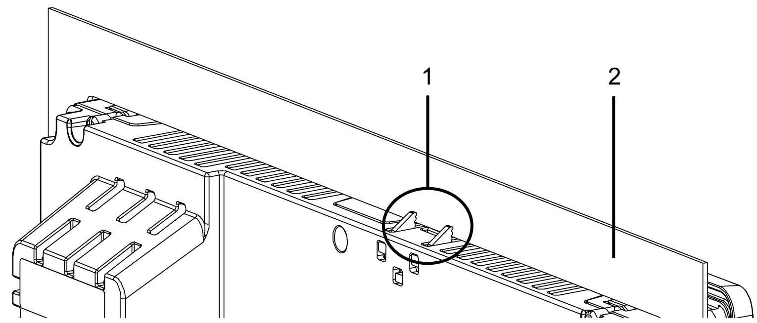
HMIDT351 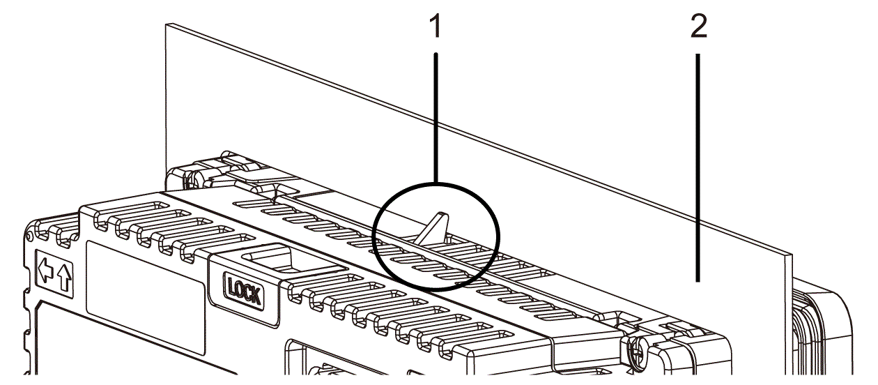
1 Anti-drop lock 2 Panel |
|
5 |
Using a Phillips screwdriver, gradually tighten (turn clockwise) the screws for the fasteners (top, bottom, left, and right), alternating diagonally between screws until all are secure. Be sure that the L-shaped part of the installation fastener (2 in figure below) is completely vertical. The necessary torque is 0.5 N•m (4.4 lb-in). NOTE: oIf the Display Module is not mounted properly, it may fall. oIf the panel is thick (approximately 5 mm [0.2 in]), you may have trouble straightening the L-shaped part of the installation fastener. If this happens, push the display module from the front as you tighten the screws. 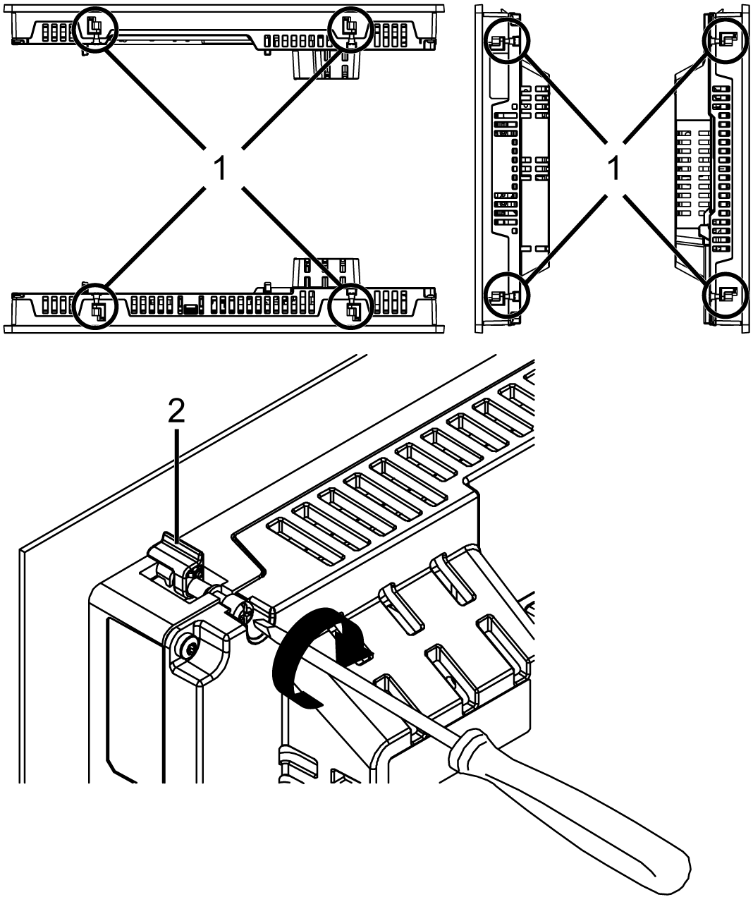
1 Installation fastener 2 L-shaped part of the installation fastener Number of Installation Fasteners 15-inch or larger models: oTop - 2, Bottom - 2, Right - 2, Left - 2 Models less than 12-inch: oTop - 2, Bottom - 2, Right - None, Left - None |
|
NOTICE |
|
BROKEN ENCLOSURE |
|
Do not exert more than 0.5 N•m (4.4 lb-in) of torque when tightening the fastener's screws. |
|
Failure to follow these instructions can result in equipment damage. |
|
NOTICE |
|
EQUIPMENT DAMAGE |
|
oWhen this product is mounted vertically, first remove the Display Module from the panel, then remove the Box Module from the Display Module. oKeep this product stabilized in the panel cutout while you are installing or removing the screw fasteners. |
|
Failure to follow these instructions can result in equipment damage. |
|
Step |
Action |
|---|---|
|
1 |
Using a Phillips screwdriver, gradually loosen (turn counterclockwise) the screws for the fasteners (top, bottom, left, and right), alternating diagonally between screws until all screws are loose. 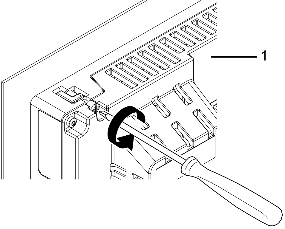
1 Rear side NOTE: oFor the number of installation fasteners on your model, see Number of Installation Fasteners in Step 5 of Installing to the Panel. oIf the panel is thick (approximately 5 mm [0.2 in]), you may have trouble straightening the L-shaped part of the installation fastener. If this happens, push the display module from the front as you loosen the screws. |
|
2 |
While pushing on the anti-drop lock on the top of the Display Module with a tool such as a screwdriver, slowly remove the Display Module from the panel. 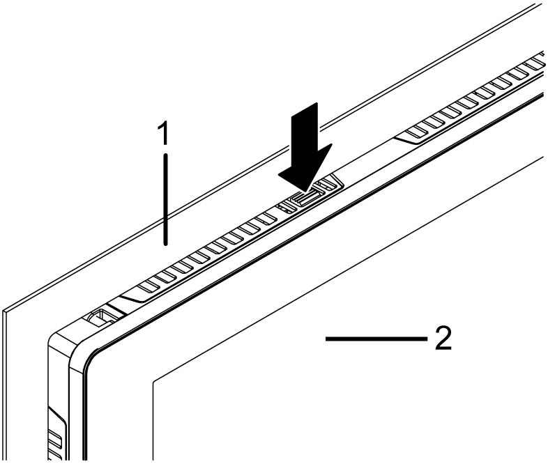
1 Panel 2 Front side |
|
NOTICE |
|
EQUIPMENT DAMAGE |
|
To avoid damage, remove this product while pushing the anti-drop lock or by making sure the lock does not touch the panel. |
|
Failure to follow these instructions can result in equipment damage. |