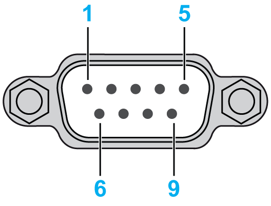
Serial Interface Specifications COM1
This interface is used to connect HMIGXO series to remote equipment, via an RS-232C cable. The connector used is a D-Sub 9-pin male connector.
By using a long PLC cable to connect to the panel, it is possible that the cable can be at a different electrical potential than the panel, even if both are grounded.
The panel’s serial port is not isolated. The SG (signal ground) and the FG (functional ground) terminals are connected inside the panel.
|
|
|
ELECTRIC SHOCK |
|
oMake a direct connection between the functional ground (FG) terminal and ground. oDo not connect other devices to ground through the functional ground (FG) terminal of this device. oInstall all cables according to local codes and requirements. If local codes do not require grounding, follow a reliable guide such as the US National Electrical Code, Article 800. |
|
Failure to follow these instructions will result in death or serious injury. |
The following table describes the serial interface with a D-Sub 9 pin connector via an RS-232C cable.
|
Pin Connection |
Pin |
Signal Name |
Direction |
Meaning |
|---|---|---|---|---|

|
1 |
CD |
Input |
Carrier Detect |
|
2 |
RD(RXD) |
Input |
Receive Data |
|
|
3 |
SD(TXD) |
Output |
Send Data |
|
|
4 |
ER(DTR) |
Output |
Data Terminal Ready |
|
|
5 |
SG |
- |
Signal Ground |
|
|
6 |
DR(DSR) |
Input |
Data Set Ready |
|
|
7 |
RS(RTS) |
Output |
Request to Send |
|
|
8 |
CS(CTS) |
Input |
Send possible |
|
|
9 |
Reserved |
Input |
– |
|
|
Shell |
FG |
– |
Functional Ground (Common with SG) |
Any excessive weight or stress on communication cables disconnect communication with the equipment.
|
|
|
LOSS OF POWER |
|
oMake sure all connections to the communication ports on the bottom and sides of the panel do not put excessive stress on the ports. oSecurely attach communication cables to the panel or cabinet. oUse only D-Sub 9 pin cables with a locking system in good condition. |
|
Failure to follow these instructions can result in injury or equipment damage. |