This section describes the configuration of Modbus TCP Slave Device to the controller.
The Modbus TCP Slave Device is a privileged Modbus device on the network. It serves as a gateway for an external I/O scanner configured as the Modbus master, and allows this scanner to exchange data with the controller without interfering with the operation of the Modbus server on the controller. Essentially, the Modbus TCP Slave allows two Modbus masters to coexist and exchange data.
While the Modbus TCP Slave Device uses standard Modbus commands (3 h, 6 h, and so on), these commands do not have their standard meaning. As this device is acting as a gateway for an external I/O scanner (Modbus master), the schema where %IW registers are associated with inputs (read-only) and %QW registers are associated with outputs (read-write) is reversed when considered from the perspective of the external Modbus master.
For further information about Modbus TCP, refer to the www.odva.org website.
Adding a Modbus TCP Slave Device
See Adding an Ethernet Manager.
To configure the Modbus TCP Slave Device, double-click Modbus > Modbus TCP in the Devices tree.
This dialog box appears:

|
Element |
Description |
|---|---|
|
IP Master Address |
IP address of the Modbus master The connections are not closed on this address. |
|
TimeOut |
Timeout in 500 ms increments NOTE: The timeout applies to the IP master Address unless the address is 0.0.0.0. |
|
Slave Port |
Modbus communication port (502) |
|
Unit ID |
Sends the requests to the Modbus TCP slave device (1...247), instead of to the embedded Modbus server (255). |
|
Holding Registers (%IW) |
Size of the %IW registers in bytes (2...40 bytes) |
|
Input Registers (%QW) |
Size of the %QW registers in bytes (2...40 bytes) |
Modbus TCP Slave Device I/O Mapping Tab
The I/Os are mapped to Modbus registers from the master perspective as follows:
o%IWs are mapped from register 0 to n-1 and are R/W (n = Holding register quantity, each %IW register is 2 bytes).
o%QWs are mapped from register n to n+m -1 and are read only (m = Input registers quantity, each %QW register is 2 bytes).
Once a Modbus TCP Slave Device has been configured, Modbus commands sent to its Unit ID (Modbus address) are handled differently than the same command would be when addressed to any other Modbus device on the network. For example, when the Modbus command 3 (3 hex) is sent to a standard Modbus device, it reads and returns the value of one or more registers. When this same command is sent to the Modbus TCP Slave, it facilitates a read operation by the external I/O scanner.
The Modbus TCP Slave Device responds to a subset of the Modbus commands, but does so in a way that differs from Modbus standards, and with the purpose of exchanging data with the external I/O scanner. The following Modbus commands are supported by the Modbus TCP slave device:
|
Function Code Dec (Hex) |
Function |
Comment |
|---|---|---|
|
3 (3) |
Read holding register |
Allows the master to read %IW and %QW objects of the device |
|
6 (6) |
Write single register |
Allows the master to write %IW objects of the device |
|
16 (10) |
Write multiple registers |
Allows the master to write %IW objects of the device |
|
23 (17) |
Read/write multiple registers |
Allows the master to read %IW and %QW objects of the device and write %IW objects of the device |
|
Other |
Not supported |
– |
NOTE: Modbus requests that attempt to access registers above n+m-1 are answered by the 02 - ILLEGAL DATA ADDRESS exception code.
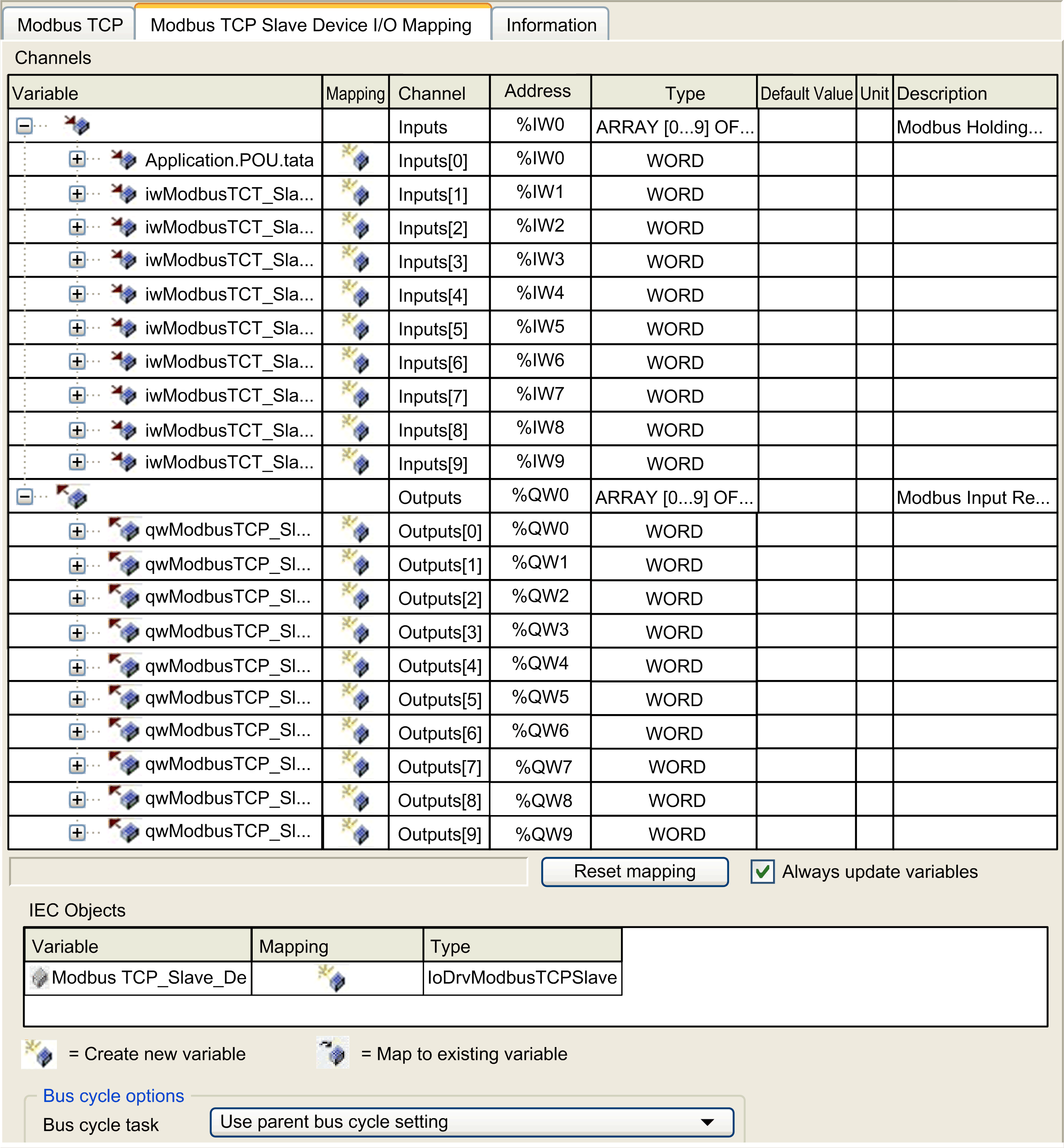
To link I/O objects to variables, select the Modbus TCP Slave Device I/O Mapping tab:

|
Channel |
Type |
Description |
|
|---|---|---|---|
|
Input |
IW0 |
WORD |
Holding register 0 |
|
... |
... |
... |
|
|
IWx |
WORD |
Holding register x |
|
|
Output |
QW0 |
WORD |
Input register 0 |
|
... |
... |
... |
|
|
QWy |
WORD |
Input register y |
|
The number of words depends on the Holding Registers (%IW) and Input Registers (%QW) parameters of the Modbus TCP tab.
NOTE: Output means OUTPUT from Originator controller (= %IW for the controller). Input means INPUT from Originator controller (= %QW for the controller).
In the Modbus TCP Slave Device I/O Mapping tab, select the Bus cycle task to use:
oUse parent bus cycle setting (the default),
oMAST
oAn existing task of the project: you can select an existing task and associate it to the scanner. For more information about the application tasks, refer to the EcoStruxure Machine Expert Programming Guide.
NOTE: There is a corresponding Bus cycle task parameter in the I/O mapping editor of the device that contains the Modbus TCP Slave Device. This parameter defines the task responsible for refreshing the %IW and %QW registers.