As standard equipment, the controller provides an embedded Web server with a predefined, built-in website. You can use the pages of the website for module setup and control as well as application diagnostics and monitoring. These pages are ready to use with a Web browser. No configuration or programming is required.
The Web server can be accessed by the web browsers listed below:
oGoogle Chrome (version 65.0 or greater)
oMozilla Firefox (version 54 or greater)
oMicrosoft Internet Explorer (version 11 or greater)
The Web server is limited to 10 TCP connections.
The Web server has full access to your application for reading and writing data and controlling the state of the controller. By enabling the Web server, you enable these functions. You can disable the Web server on an interface by deselecting the Web Server active parameter in the Ethernet Configuration tab.
The Web server is a tool for reading and writing data, and controlling the state of the controller, with full access to all data in your application. However, if there are security concerns over these functions, you must at a minimum assign a secure password to the Web Server or disable the Web server to help prevent unauthorized access to the application. By enabling the Web server, you enable these functions.
The Web server allows you to monitor a controller and its application remotely, to perform various maintenance activities including modifications to data and configuration parameters, and change the state of the controller. Care must be taken to ensure that the immediate physical environment of the machine and process is in a state that will not present safety risks to people or property before exercising control remotely.
|
|
|
UNINTENDED EQUIPMENT OPERATION |
|
oConfigure and install the RUN/STOP input for the application, if available for your particular controller, so that local control over the starting or stopping of the controller can be maintained regardless of the remote commands sent to the controller. oDefine a secure password for the Web Server and do not allow unauthorized or otherwise unqualified personnel to use this feature. oEnsure that there is a local, competent, and qualified observer present when operating on the controller from a remote location. oYou must have a complete understanding of the application and the machine/process it is controlling before attempting to adjust data, stopping an application that is operating, or starting the controller remotely. oTake the precautions necessary to assure that you are operating on the intended controller by having clear, identifying documentation within the controller application and its remote connection. |
|
Failure to follow these instructions can result in death, serious injury, or equipment damage. |
NOTE: The Web server must only be used by authorized and qualified personnel. A qualified person is one who has the skills and knowledge related to the construction and operation of the machine and the process controlled by the application and its installation, and has received safety training to recognize and avoid the hazards involved. No responsibility is assumed by Schneider Electric for any consequences arising out of the use of this feature.
Access to the Web server is controlled by User Rights when they are enabled in the controller. For more information, refer to Users and Groups Tab Description.
To access the Web server you must first connect to the controller with EcoStruxure Machine Expert or Controller Assistant and modify the default user password.
|
|
|
UNAUTHORIZED DATA ACCESS |
|
oSecure access to the FTP/Web server using User Rights. oIf you disable User Rights, disable the FTP/Web server to help prevent any unwanted or unauthorized access to data in your application. |
|
Failure to follow these instructions can result in death, serious injury, or equipment damage. |
In order to change the password, go to Users and Groups tab of the device editor. For more information, refer to the EcoStruxure Machine Expert Programming Guide.
NOTE: The only way to gain access to a controller that has user access-rights enabled and for which you do not have the password(s) is by performing an Update Firmware operation. This clearing of User Rights can only be accomplished by using a USB key to update the controller firmware. In addition, you may clear the User Rights in the controller by running a script (for more information, refer to EcoStruxure Machine Expert Programming Guide) . This effectively removes the existing application from the controller memory, but restores the ability to access the Controller.
To access to the website home page shown in the following illustration, type in your navigator the IP address of the controller, or 90.0.0.1 for a USB connection:
This figure shows the Web Server site login page:
This figure shows the home page of the Web Server site once you have logged in:

NOTE: Schneider Electric adheres to industry best practices in the development and implementation of control systems. This includes a "Defense-in-Depth" approach to secure an Industrial Control System. This approach places the controllers behind one or more firewalls to restrict access to authorized personnel and protocols only.
|
|
|
UNAUTHENTICATED ACCESS AND SUBSEQUENT UNAUTHORIZED MACHINE OPERATION |
|
oEvaluate whether your environment or your machines are connected to your critical infrastructure and, if so, take appropriate steps in terms of prevention, based on Defense-in-Depth, before connecting the automation system to any network. oLimit the number of devices connected to a network to the minimum necessary. oIsolate your industrial network from other networks inside your company. oProtect any network against unintended access by using firewalls, VPN, or other, proven security measures. oMonitor activities within your systems. oPrevent subject devices from direct access or direct link by unauthorized parties or unauthenticated actions. oPrepare a recovery plan including backup of your system and process information. |
|
Failure to follow these instructions can result in death, serious injury, or equipment damage. |
The generic menu bar lets you access the main Web server pages.
The Web Server contains the following pages:
|
Menu |
Page |
Description |
|---|---|---|
|
Home |
Home page of the controller Web server page. Provides access to the tabs: oMonitoring oDiagnostics oMaintenance oSetup |
|
|
Documentation |
References |
Link to the brand site. |
:
|
Menu |
Submenu |
Description |
|---|---|---|
|
Monitoring |
oSerial Number oVersion (firmware, boot...) oConfiguration status |
|
|
Shows the status of expansion modules. |
||
|
Shows the module with module I/O values. |
||
|
Displays 2 variables in the form of a recorder-type time chart. |
||
|
Lets you display and modify controller variables. |
||
|
Diagnostics |
Controller status |
|
|
Ethernet status |
||
|
Serial line status |
||
|
Profibus status |
||
|
Maintenance |
Link to the file system server (/Usr, /bd0 and /Sys folders) |
|
|
Lets you change user password and customize login message. oUsers account management: allows you to remove all passwords from the controller and reset user accounts to their default state. oClone management: lets you include or exclude user access rights when cloning a controller. |
||
|
Setup |
Lets you set the Ethernet and serial line parameters. |
|
|
Lets you set the EthernetIP configuration files. |
The following submenu is visible in each tab:
|
Submenu |
Description |
|---|---|
|
Info |
Current Controller information oReference oDevice name oRunning state |
|
Control |
Allows you to Start or Stop the controller |
The Web server allows you to remotely monitor a controller and its application, and to perform various maintenance activities including modifications to data and configuration parameters, and change the state of the controller. Ensure that the immediate physical environment of the machine and process is in a state that will not present safety risks to people or property before exercising control remotely.
|
|
|
UNINTENDED EQUIPMENT OPERATION |
|
oConfigure and install the RUN/STOP input for the application, if available for your particular controller, so that local control over the starting or stopping of the controller can be maintained regardless of the remote commands sent to the controller. oDefine a secure password for the Web Server and do not allow unauthorized or otherwise unqualified personnel to use this feature. oEnsure that there is a local, competent, and qualified observer present when operating on the controller from a remote location. oYou must have a complete understanding of the application and the machine/process it is controlling before attempting to adjust data, stopping an application that is operating, or starting the controller remotely. oTake the precautions necessary to assure that you are operating on the intended controller by having clear, identifying documentation within the controller application and its remote connection. |
|
Failure to follow these instructions can result in death, serious injury, or equipment damage. |
NOTE: The Web server must only be used by authorized and qualified personnel. A qualified person is one who has the skills and knowledge related to the construction and operation of the machine and the process controlled by the application and its installation, and has received safety training to recognize and avoid the hazards involved. No responsibility is assumed by Schneider Electric for any consequences arising out of the use of this feature.
This table lists the necessary status of the controller to access different pages:
|
Menu |
Submenu |
Controller State |
|||
|---|---|---|---|---|---|
|
EMPTY |
STOPPED |
RUNNING |
HALT |
||
|
Home |
Home |
X |
X |
X |
X |
|
Documentation |
References |
X |
X |
X |
X |
|
Monitoring |
Controller Viewer |
X |
X |
X |
X |
|
Expansion Viewer |
- |
X |
X |
- |
|
|
IO Viewer |
- |
X |
X |
- |
|
|
Oscilloscope |
- |
X |
X |
- |
|
|
Data parameters |
- |
X |
X |
- |
|
|
Diagnostics |
Controller diagnostic |
X |
X |
X |
X |
|
Ethernet diagnostic |
X |
X |
X |
X |
|
|
Serial diagnostic |
X |
X |
X |
X |
|
|
Profibus diagnostic |
X |
X |
X |
X |
|
|
Maintenance |
/Usr or /bd0 |
X |
X |
X |
X |
|
/Sys |
X |
X |
X |
X |
|
|
Setup |
Post configuration setup |
X |
X |
X |
X |
|
EthernetIP configurations files |
X |
X |
X |
X |
|
Monitoring: Controller Viewer Submenu
The Controller Viewer submenu shows the controller status:
The Configuration status field can change depending on the controller reference visualized (a LMC058LF424 in the previous screenshot) and can have the following status:
|
Configuration Status |
Description |
|---|---|
|
No error |
No error detected on the corresponding element. |
|
Error |
An error is detected on the corresponding element. |
Monitoring: Expansion Viewer Submenu
The Expansion Viewer submenu shows the expansion module status:
The following table describes each status code:
|
Status Code |
Description |
|---|---|
|
0 |
INACTIVE: module inactive |
|
10 |
BOOT: boot state |
|
11 |
FWDNLD: firmware download in progress |
|
20 |
PREOP: basic initialization |
|
30 |
OPERATE: register initialization |
|
100 |
ACTIVE: module communication active |
|
200 |
ERROR: an error has been detected |
|
201 |
UNSUP: unsupported module |
|
202 |
NOCFG: no configuration available |
Monitoring Web Server Variables
To monitor Web server variables, you must add a Web Data Configuration object to your project. Within this object, you can select all variables you want to monitor.
This table describes how to add a Web Data Configuration object:
|
Step |
Action |
|---|---|
|
1 |
Right click the Application node in the Applications tree tab. |
|
2 |
Click Add Object > Web Data Configuration.... Result: The Add Web Data Configuration window is displayed. |
|
3 |
Click Add. Result: The Web Data Configuration object is created and the Web Data Configuration editor is open. NOTE: As a Web Data Configuration object is unique for a controller, its name cannot be changed. |
Web Data Configuration Editor
Click the Refresh button to be able to select variables, this action will display all the variables defined in the application.
Select the variables you want to monitor in the web server:
NOTE: The variable selection is possible only in offline mode.
Monitoring: Data Parameters Submenu
The Data Parameters submenu allows you to display and modify variable values:
|
Element |
Description |
|---|---|
|
Add |
Adds a list description or a variable |
|
Del |
Deletes a list description or a variable |
|
Refresh period |
Refreshing period of the variables contained in the list description (in ms) |
|
Refresh |
Enables I/O refreshing: oGray button: refreshing disabled oOrange button: refreshing enabled |
|
Load |
Loads saved lists from the controller internal Flash to the Web server page |
|
Save |
Saves the selected list description in the controller (/usr/web or /bd0/web directory) |
NOTE: IEC objects (%IW, %M,...) are not directly accessible. To access IEC objects you must first group their contents in located registers (refer to Relocation Table).
The IO Viewer submenu allows you to display and modify the current I/O values:
|
Element |
Description |
|---|---|
|
Refresh |
Enables I/O refreshing: oGray button: refreshing disabled oOrange button: refreshing enabled |
|
|
I/O refreshing period in ms |
|
<< |
Goes to previous I/O list page |
|
>> |
Goes to next I/O list page |
Monitoring: Oscilloscope Submenu
The oscilloscope submenu can display up to 2 variables in the form of a recorder time chart:
|
Element |
Description |
|---|---|
|
Reset |
Erases the memorization |
|
Refresh |
Starts/stops refreshing |
|
Load |
Loads parameter configuration of Item0 and Item1 |
|
Save |
Saves parameter configuration of Item0 and Item1 in the controller |
|
Item0 |
Variable to be displayed |
|
Item1 |
Variable to be displayed |
|
Min |
Minimum value of the variable axis |
|
Max |
Maximum value of the variable axis |
|
Period(ms) |
Page refresh period in milliseconds |
Diagnostic: Controller Submenu
The Controller submenu displays information of the current status of the controller:
The Ethernet submenu displays Ethernet communication information:
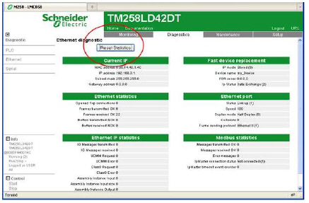
The Reset Statistic button sets the Ethernet statistics to 0.
The Serial submenu displays the serial line communication information:
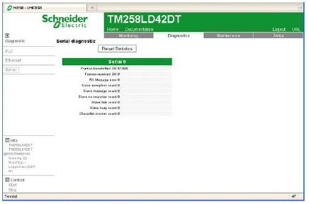
The Reset Statistics button sets the statistics of the serial connections to 0.
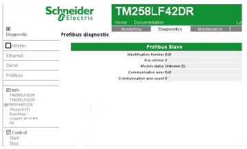
The Profibus submenu is available for controllers with PCI module. It displays the Profibus communication information:
The Maintenance page provides access to the /usr, /bd0 and /sys folders of the controller flash memory:
Index of /usr or /bd0:
Index of /sys:

|
|
|
UNINTENDED WEB SERVER AND CONTROLLER BEHAVIOR |
|
Do not modify any of the files in the /usr and /sys directories. |
|
Failure to follow these instructions can result in death, serious injury, or equipment damage. |
The Post Conf submenu allows you to update the PostConf file saved on the controller:
|
Step |
Action |
|---|---|
|
1 |
Click Load. |
|
2 |
|
|
3 |
Click Save. NOTE: The new parameters will be considered at next Post Configuration file reading. |
Setup: Ethernet IP configurations File Submenu
The file tree only appears when the Ethernet IP service is configured on the controller.
Index of /usr or /bd0:
|
File |
Description |
|---|---|
|
My Machine Controller.gz |
GZIP file |
|
My Machine Controller.ico |
Icon file |
|
My Machine Controller.eds |
Electronic Data Sheet file |
Maintenance: User Management Submenu
The User Management submenu displays a screen that allows you to access two different actions:
oUser accounts management:
Allows you to manage user accounts management, removing passwords and returning the user accounts on the controller to default settings.
Click Disable to remove passwords on the controller.
Click OK on the window that appears to confirm. As a result:
oUsers no longer have to set and enter a password to connect to the controller.
oFTP and HTTP connections accept anonymous user connections.
NOTE: The Disable button is only active if the current user has administrative privileges.
Click Reset to default to return the user accounts on the controller to their default setting state.
Click OK on the window that appears to confirm.
NOTE: Connections to FTP and HTTP are blocked until a new password is set.
oClone management:
allows you to control whether user rights are copied and applied to the target controller when cloning a controller with a USB key.
Click Exclude users rights to exclude copying user rights to the target controller when cloning a controller.
NOTE: By default, the users rights are excluded.
Click Include users rights to copy user rights to the target controller when cloning a controller. A popup prompts you to confirm copying the user rights. Click OK to continue.
