The Modicon M218 Logic Controller features digital inputs, including 4 fast inputs, except the references below which have 2 fast inputs:
oTM218LDA16DRN
oTM218LDA24DRN
oTM218LDA40DRN
oTM218LDA60DRN
The following functions are configurable on standard and/or fast inputs:
oFilters (depends on the function associated with the input).
o4 fast inputs can be either latched or used for events (rising edge, falling edge, or both) and thus be linked to an external task.
oAny input can be used for the RUN/STOP function.
oSome of the inputs can be used by HSC, PTO, PWM, and FG functions.
NOTE: All inputs by default can be used as regular inputs.
The integrator filter is designed to reduce the effect of noise. Setting a filter value allows the controller to ignore sudden changes of input levels caused by noise.
The following timing diagram illustrates the integrator filter effects for a value of 4 ms:
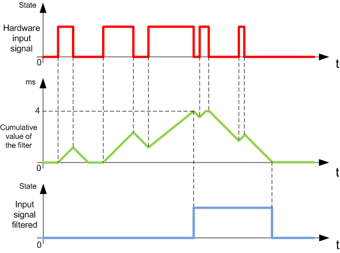
NOTE: The value selected for the filters time parameter specifies the cumulative time in ms that must elapse before the input can be 1.
The bounce filter is designed to reduce the bouncing effect at the inputs. Setting a bounce filter value allows the controller to ignore sudden changes of input levels caused by noise. The bounce filter is only available on the fast inputs.
The following timing diagram illustrates the anti-bounce filter effects:
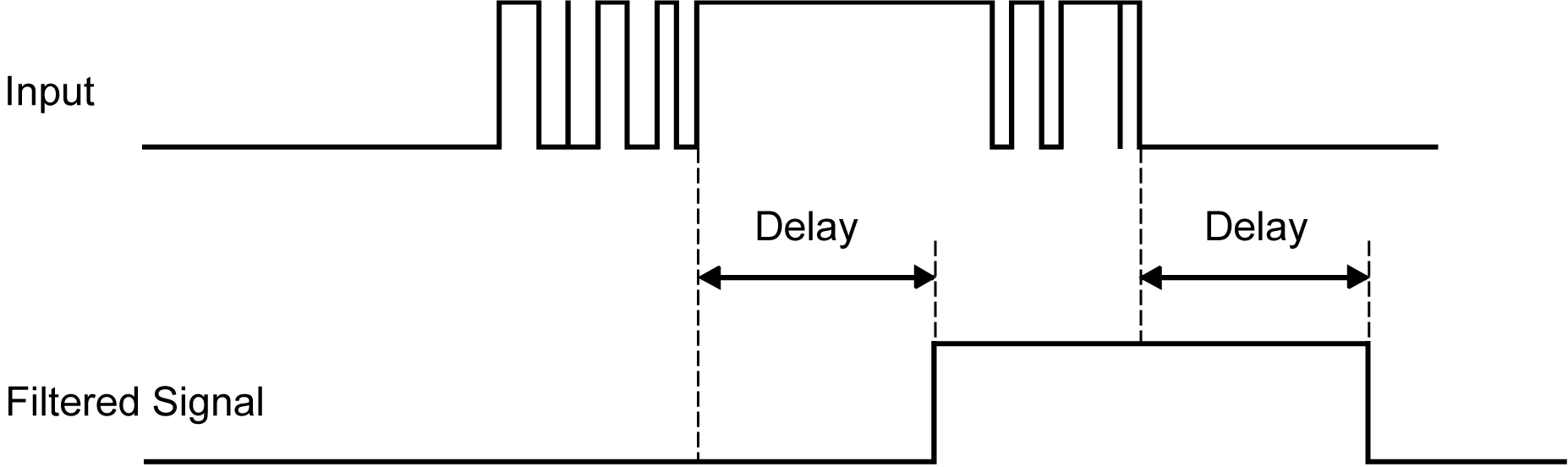
The bounce filter can be used on a fast input when:
oUsing a latch or event
oNo HSC is enabled
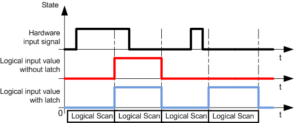
Latching is a function that can be assigned to the Modicon M218 Logic Controller fast inputs. This function is used to memorize (or latch) any pulse with a duration that is less than the Modicon M218 Logic Controller scan time. When a pulse is shorter than one scan, the controller latches the pulse, which is then updated in the next scan. This latching mechanism only recognizes rising edges. Falling edges cannot be latched. Assigning inputs to be latched is done with the I/O configuration display in EcoStruxure Machine Expert.
The following timing diagram illustrates the latching effects:
An input configured for Event can be associated with an External Task.
The RUN/STOP function is used to start or stop a program using an input:
oWhen the configured RUN/STOP input is at logic 0, the controller is put into a STOP state and any outside command to enter the RUN state is ignored.
oA rising edge (passing from 0 to 1) of the RUN/STOP input provokes automatically a start-up of the application as the controller enters a RUN state.
oWhen the configured RUN/STOP input is at logic 1, then the controller program is running unless otherwise commanded by EcoStruxure Machine Expert (RUN/STOP commands from EcoStruxure Machine Expert are allowed).
|
|
|
UNINTENDED MACHINE OR PROCESS START-UP |
|
oVerify the state of security of your machine or process environment before applying power to the Run/Stop input. oUse the Run/Stop input to help prevent the unintentional start-up from a remote location. |
|
Failure to follow these instructions can result in death, serious injury, or equipment damage. |
For more information, refer to Embedded I/O configuration.
