The serial link port 1 is used to communicate with devices supporting the Modbus protocol as either a master or slave, ASCII Protocol (printer, modem...), and EcoStruxure Machine Expert Protocol (HMI,...).
|
Characteristic |
Description |
|
|---|---|---|
|
Function |
Modbus Master/Slave NOTE: Slave mode needs 120 Ω resistor for external line termination. |
|
|
Connector type |
RJ45 |
|
|
Isolation |
Non-isolated |
|
|
Maximum baud rate |
115,200 bps |
|
|
Cable |
Type |
Shielded |
|
Maximum length |
15 m (49 ft) |
|
|
Polarization |
Software configuration is used to connect when the node is configured as a Master. 560 Ω resistors are optional. |
|
|
5 Vdc power supply for RS485 |
No |
|
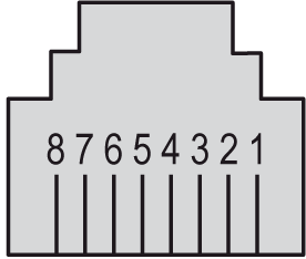
The following illustration shows the pins of the RJ45 connector:

The table below describes the pin assignment of the RJ45 connector:
|
Pin |
|
|---|---|
|
1 |
N.C. |
|
2 |
N.C. |
|
3 |
N.C. |
|
4 |
D1 |
|
5 |
D0 |
|
6 |
N.C. |
|
7 |
N.C. |
|
8 |
Common |
N.C.: Not Connected
|
|
|
UNINTENDED EQUIPMENT OPERATION |
|
Do not connect wires to unused terminals and/or terminals indicated as “No Connection (N.C.)”. |
|
Failure to follow these instructions can result in death, serious injury, or equipment damage. |

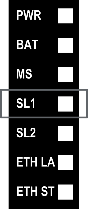
The table below describes the serial link port 1 status LED:
|
Label |
Description |
LED |
||
|---|---|---|---|---|
|
Color |
Status |
Description |
||
|
SL1 |
Serial Link 1 |
Yellow |
On |
Indicates the activity of the serial link 1 |
|
Off |
Indicates no serial communication |
|||