The TM218LDA40DR2HN controller is equipped with 2 analog outputs.
|
|
|
FIRE HAZARD |
|
Use only the correct wire sizes for the current capacity of the power supplies. |
|
Failure to follow these instructions will result in death or serious injury. |
|
|
|
UNINTENDED EQUIPMENT OPERATION |
|
Do not exceed any of the rated values specified in the environmental and electrical characteristics tables. |
|
Failure to follow these instructions can result in death, serious injury, or equipment damage. |
The table below describes the characteristics of the Modicon M218 Logic Controller analog outputs:
|
Characteristic |
Voltage output |
Current output |
|
|---|---|---|---|
|
Maximum number of outputs |
2 |
||
|
Output range |
-10... +10 Vdc/0...+10 Vdc |
0...20 mA / 4...20 mA |
|
|
Connectable I/O terminals |
Removable terminals |
||
|
Load impedance |
> 2 kΩ |
> 300 Ω |
|
|
Application load type |
Resistive load |
||
|
Setting time |
10 ms |
||
|
Total output system transfer time |
10 ms + 1 scan time |
||
|
Output tolerance |
Maximum deviation at 25 °C (77 °F) without electromagnetic disturbance |
± 1% of the full scale |
|
|
Maximum deviation |
± 2.5% of the full scale |
||
|
Digital resolution |
12 bits, including sign |
||
|
Temperature drift |
± 0.06% of the full scale |
||
|
Output ripple |
±50 mV |
||
|
Cross talk |
60 db |
||
|
Non-linearity |
± 0.5% of the full scale |
||
|
Output value of LSB |
6 mV |
10 μΑ |
|
|
Protection type |
Photo coupler between input and internal circuit |
||
|
Output protection |
short-circuit protection |
Open circuit protection |
|
|
Output behavior if input power supply is less than the power threshold |
Set to 0 |
||
|
Cable |
Type |
Shielded |
|
|
Length |
3 m (9.84 ft) NOTE: Compliance to electromagnetic immunity standards is limited to a 3 m (9.84 ft) cable length. In all cases, a maximum cable length of 10 m (32.80 ft) should not be exceeded. |
||
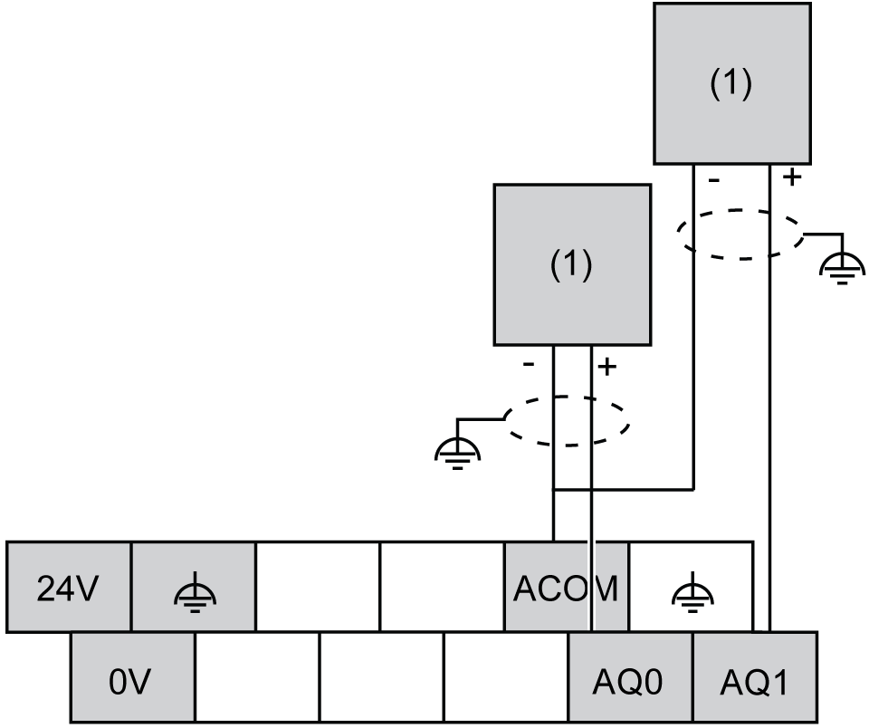
The following illustration shows the wiring diagram of the Modicon M218 Logic Controller analog outputs:

(1) Voltage/Current preactuator
|
|
|
UNINTENDED EQUIPMENT OPERATION |
|
Do not connect wires to unused terminals and/or terminals indicated as “No Connection (N.C.)”. |
|
Failure to follow these instructions can result in death, serious injury, or equipment damage. |
|
|
|
UNINTENDED EQUIPMENT OPERATION |
|
oUse shielded cables for all fast I/O, analog I/O, and communication signals. oGround cable shields for all fast I/O, analog I/O, and communication signals at a single point1. oRoute communications and I/O cables separately from power cables. |
|
Failure to follow these instructions can result in death, serious injury, or equipment damage. |
1Multipoint grounding is permissible if connections are made to an equipotential ground plane dimensioned to help avoid cable shield damage in the event of power system short-circuit currents.
For more information, refer to the TM218 System Wiring Rules and Recommendation.
|
NOTICE |
|
INOPERABLE EQUIPMENT |
|
Verify that the physical wiring of the analog circuit is compatible with the software configuration for the analog channel. |
|
Failure to follow these instructions can result in equipment damage. |