2 PTO channels can be configured on the controller.
Each PTO channel configured uses to 2 fast transistor outputs and 2 digital inputs.The PTO function is only available on controllers supporting fast transistor outputs..
|
Step |
Action |
|---|---|
|
1 |
In the Devices tree, double-click MyController > Embedded Functions > PTO_PWM. |
|
2 |
Select the PTO x tab corresponding to the channel to be configured. |
|
3 |
The instance of the PTO is created, it can be renamed in the Variable field. Default names are: PTO00 and PTO01. |
Configuration Window Description
This table describes each parameter available when the embedded PTO_PWM is configured in PTO mode:
|
Parameter |
Value |
Default Value |
Unit |
Description |
|
|---|---|---|---|---|---|
|
Mode |
PTO |
PTO |
- |
The Mode selected is PTO. |
|
|
Pulse/Direction Direction/Pulse ClockWise/CounterClockWise CounterClockWise/ClockWise |
Pulse/Direction |
- |
Mode of generation of outputs |
||
|
Acc./Dec. Unit |
ms Hz/ms |
ms |
- |
Acceleration/Deceleration Unit |
|
|
Acc. max. |
20...65000 |
20 |
- |
Acceleration rate maximum value |
|
|
Dec. max. |
20...65000 |
20 |
- |
Deceleration rate maximum value |
|
|
Dec. Fast Stop |
20...32500 |
100 |
- |
Deceleration rate used in case of a fast stop. (Drive Ready input low, limits exceeded, detected errors) |
|
|
Start |
0...65535 |
0 |
Hz |
Start frequency. 0 = no use of start frequency parameter. |
|
|
Stop |
0...65535 |
0 |
Hz |
Stop frequency. 0 = no use of stop frequency parameter. |
|
|
Maximum |
1...100000 |
100000 |
Hz |
Maximum frequency |
|
|
AUX |
Not used Drive Ready Origin |
Not used |
- |
Specific input dedicated to the Drive Ready information or to the reference point detection (origin) |
|
|
AUX Filter |
0.02 0.4 1.2 4 |
0.02 |
Filtering value reduces the effect of bounce on the auxiliary input |
||
|
PROX |
Disabled Enabled |
Disabled |
- |
Specific input dedicated to the Proximate input |
|
|
PROX Filter |
0.02 0.4 1.2 4 |
0.02 |
ms |
Filtering value reduces the effect of bounce on the proximate input |
|
|
Homing Acc. |
20...65000 |
500 |
ms |
Acceleration during homing (≤ Acc. max.) |
|
|
Homing Dec. |
20...65000 |
500 |
ms |
Deceleration during homing (≤ Dec. max.) |
|
|
Minimum |
-2147483648... 2147483647 |
-2147483648 |
- |
Minimum software limit) |
|
|
Maximum |
-2147483648...2147483647 |
2147483647 |
- |
Maximum software limit) |
|
|
Step |
Action |
|---|---|
|
1 |
Enable the PTO channel: In the list box Mode parameter > select PTO. |
|
2 |
In the list box Output Mode parameter > Select the Mode of generation of outputs in the value column. |
|
3 |
Configure the Acc./Dec. Unit, Acc.max, Dec. max, and Dec. Fast stop parameters. |
|
4 |
Configure the Frequency (= Velocity) parameters (Start, Stop, and Maximum). |
|
5 |
Enable the AUX input. |
|
6 |
Configure the AUX input filtering value (if enabled at step 5). |
|
7 |
If you have selected Origin in AUX input, then configure the Homing Acceleration/Deceleration parameters. |
|
8 |
Enable the PROX input if you need, and select the PROX Filter for it. |
|
9 |
Configure the Minimum and Maximum value for Software Limit. |
The configuration defined can be viewed as a configuration profile:
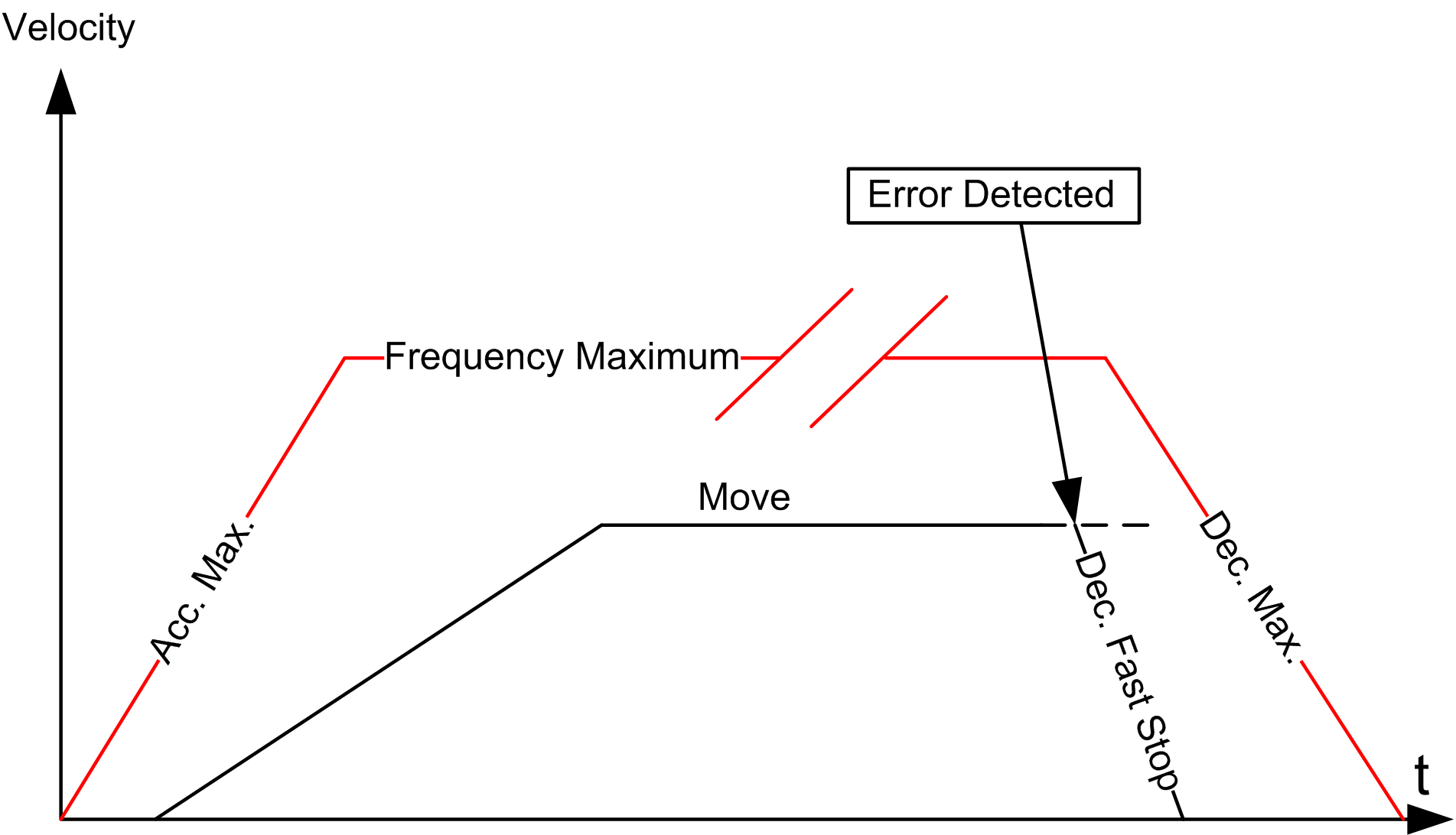
An error is detected because the Dec. Fast Stop rate is greater than the Dec. max. as it appears in this diagram.