To configure the CAN bus of your controller, refer to CAN Bus Configuration.
The CAN bus format is CAN2.0B for J1939.
J1939 Manager Creation and Configuration
|
Step |
Action |
|---|---|
|
1 |
Click the Plus button |
|
2 |
In the Add Device window, select J1939_Manager and click the Add Device button. For more information on adding a device to your project, refer to: • Using the Drag-and-drop Method • Using the Contextual Menu or Plus Button |
|
3 |
Close the Add Device window. |
|
4 |
Double-click J1939_Manager (J1939_Manager). Result: The J1939_Manager configuration window appears: 
|
|
5 |
To configure the J1939_Manager, refer to Programming with EcoStruxure Machine Expert / Device Editors / J1939 Configuration Editor / J1939 Manager Editor / Manager Editor found in the EcoStruxure Machine Expert online help. |
ECU Creation and Configuration
|
Step |
Action |
|---|---|
|
1 |
Click the Plus button |
|
2 |
In the Add Device window, select J1939_ECU and click the Add Device button. For more information on adding a device to your project, refer to: • Using the Drag-and-drop Method • Using the Contextual Menu or Plus Button |
|
3 |
Close the Add Device window. |
|
4 |
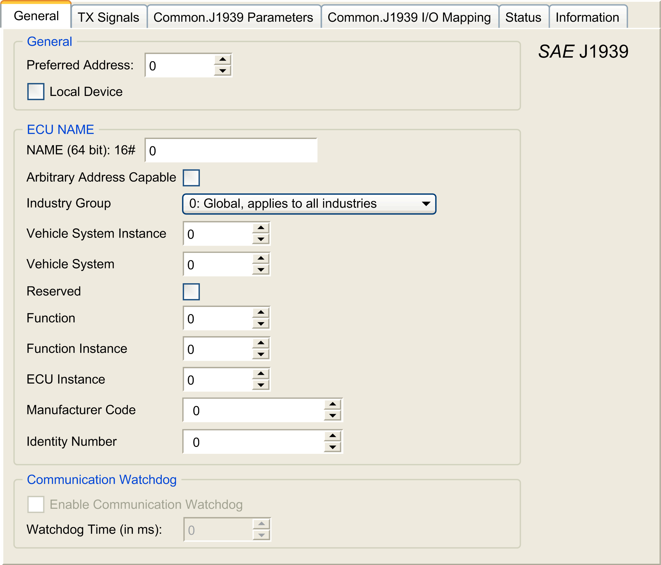
Double-click J1939_ECU (J1939_ECU). Result: The J1939_ECU configuration window appears: 
|
|
5 |
To configure the J1939_ECU, refer to Configuring J1939 ECUs. |
As an overview, the following tasks must be generally accomplished:
oAdd one J1939_ECU node for each physical J1939 device connected on the CAN bus.
oFor each J1939 device, specify a unique Preferred Address in the range 1...253.
oFor each J1939 device, configure the signals (SPNs) in the TX Signals tab. These signals are broadcast by the J1939 device to the other J1939 devices.
Refer to the device documentation for information on the supported SPNs.
oAssociate the SPN signals with variables in the J1939 I/O Mapping tab so that they can be processed by the application.
oWhen signals have been added, verify their settings in the Conversion window of the TX signals tab, for example, Scaling, Offset, and Unit. The J1939 protocol does not directly support REAL values, which are instead encoded in the protocol and so must be converted in the application. Similarly, in J1939 units are defined according to the International System of Units (SI) and therefore may need to be converted to values of other unit systems.
Examples:
oThe Engine Speed signal of parameter group EEC1 has a property Scaling=0.125 that is encoded into a raw variable of type ARRAY[0..1] OF BYTE. Use the following ST code to convert this to a REAL variable:
rRPM:=(Engine_Speed[1]*256 + Engine_Speed[0])*0.125;
oThe Total Vehicle Distance signal has properties Scaling=0.125 and Unit=km, which are received in a (raw) variable of type ARRAY[0..3] OF BYTE. Use the following ST code to convert this to a REAL variable in mile units:
rTVD := (Total_Vehicle_Distance[3]*EXPT(256,3) +
Total_Vehicle_Distance[2]*EXPT(256,2) + Total_Vehicle_Distance[1]*256 +
Total_Vehicle_Distance[0])*0.125*0.621371;
oThe Engine Coolant Temperature signal of parameter group ET1 has properties Offset=-40 and Unit=C(Celsius), which are received in a (raw) variable of type BYTE. Use the following ST code to convert it to a REAL variable in Fahrenheit units:
rEngineCoolantTemperature := (Engine_Coolant_Temperature - 40)*1.8 + 32;
For more details on how to configure the J1939_ECU, refer to Programming with EcoStruxure Machine Expert / Device Editors / J1939 Configuration Editor / J1939 ECU Editor / ECU Editor found in the EcoStruxure Machine Expert online help.
Configuring the M241 Logic Controller as an ECU Device
|
Step |
Action |
|---|---|
|
1 |
Add a J1393_ECU node to the J1939_Manager. Refer to ECU Creation and Configuration. |
|
2 |
Select the Local Device option in the General tab. |
|
3 |
Configure signals sent from the controller to other J1939 devices in the TX Signals tab. Parameter groups are either of type Broadcast, that is, sent to all devices, or P2P (Peer-to-Peer), that is, sent to one specified device. |
|
4 |
For P2P signals, configure the Destination Address of the receiving J1939 ECU device in the parameter group properties window. |
|
5 |
Add P2P signals sent by another J1939 device to the controller in the RX Signals (P2P) tab of the J1939 (local) device representing the controller. |
|
6 |
Configure the Source Address of the parameter group by specifying the address of the sending J1939 device. |