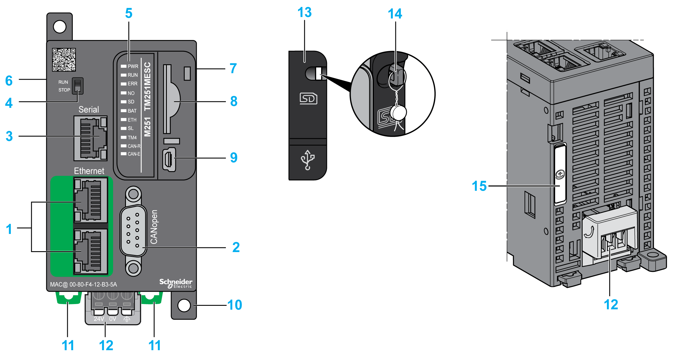
This figure shows the different components of the TM251MESC logic controller:
|
N° |
Description |
Refer to |
|---|---|---|
|
1 |
Dual port Ethernet switch |
|
|
2 |
CANopen port |
CANopen port |
|
3 |
Serial line port / Type RJ45 (RS-232 or RS-485) |
|
|
4 |
Run/Stop switch |
|
|
5 |
Status LEDs |
– |
|
6 |
TM4 bus connector |
|
|
7 |
TM3/TM2 bus connector |
|
|
8 |
SD card slot |
|
|
9 |
USB mini-B programming port / For terminal connection to a programming PC (EcoStruxure Machine Expert) |
|
|
10 |
Surface mounting lugs |
– |
|
11 |
Clip-on lock for 35 mm (1.38 in.) top hat section rail (DIN-rail) |
|
|
12 |
24 Vdc power supply |
|
|
13 |
Protective cover (SD card slot and USB mini-B programming port) |
– |
|
14 |
Locking hook (Hook not included) |
– |
|
15 |
Battery holder |
This figure shows the status LEDs:
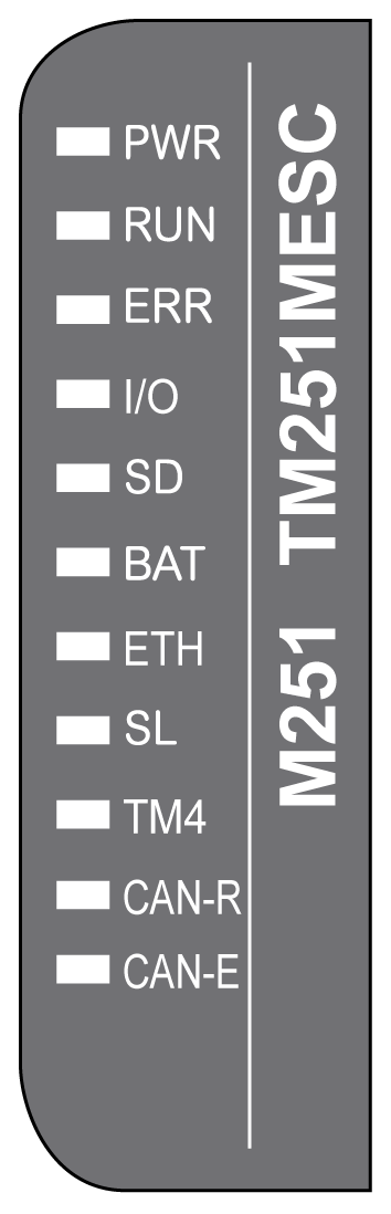
The following table describes the system status LEDs:
|
Label |
Function Type |
Color |
Status |
Description |
||
|---|---|---|---|---|---|---|
|
PWR |
Power |
Green |
On |
Indicates that power is applied. |
||
|
Off |
Indicates that power is removed. |
|||||
|
RUN |
Machine status |
Green |
On |
Indicates that the controller is running a valid application. |
||
|
Flashing |
Indicates that the controller has a valid application that is stopped. |
|||||
|
1 flash |
Indicates that the controller has paused at BREAKPOINT. |
|||||
|
Off |
Indicates that the controller is not programmed |
|||||
|
ERR |
Internal Error |
Red |
On |
Indicates that an operating system error has been detected |
||
|
Fast flashing |
Indicates that the controller has detected an internal error |
|||||
|
Slow flashing |
Indicates either that a minor error has been detected if RUN is ON or that no application has been detected |
|||||
|
I/O |
I/O error |
Red |
On |
Indicates device errors on the serial line, SD card, TM4 bus, TM3 bus, Ethernet port(s) or CANopen port. |
||
|
SD |
SD card access |
Green |
On |
Indicates that the SD card is being accessed |
||
|
BAT |
Battery |
Red |
On |
Indicates that the battery needs to be replaced. |
||
|
Flashing |
Indicates that the battery charge is low. |
|||||
|
ETH |
Ethernet port status |
Green |
On |
Indicates that the ethernet port is connected and the IP address is defined. |
||
|
3 flashes |
Indicates that the ethernet port is not connected. |
|||||
|
4 flashes |
Indicates that the IP address is already in used. |
|||||
|
5 flashes |
Indicates that the module is waiting for BOOTP or DHCP sequence. |
|||||
|
6 flashes |
Indicates that the configured IP address is not valid. |
|||||
|
SL |
Serial line |
Green |
On |
Indicates the status of serial line |
||
|
Off |
Indicates no serial communication |
|||||
|
TM4 |
Error on TM4 bus |
Red |
On |
Indicates that an error has been detected on the TM4 bus |
||
|
Off |
Indicates that no error has been detected on the TM4 bus |
|||||
|
CAN-R |
CANopen running status |
Green |
On |
Indicates that the CANopen bus is operational. |
||
|
Off |
Indicates that the CANopen master is configured. |
|||||
|
Flashing |
Indicates that the CANopen bus is being initialized. |
|||||
|
1 flash per second |
Indicates that the CANopen bus is stopped. |
|||||
|
CAN-E |
CANopen error |
Red |
On |
Indicates that the CANopen bus is stopped (BUS OFF). |
||
|
Off |
Indicates no CANopen detected error. |
|||||
|
Flashing |
Indicates that the CANopen bus is not valid. |
|||||
|
1 flash per second |
Indicates that the controller has detected that the maximum number of error frames has been reached or exceeded. |
|||||
|
2 flashes per second |
Indicates that the controller has detected either a Node Guarding or a Heartbeat event. |
|||||
NOTE: All the LEDs flash when the logic controller is being identified. For more details, refer to the EcoStruxure Machine Expert Programming Guide.
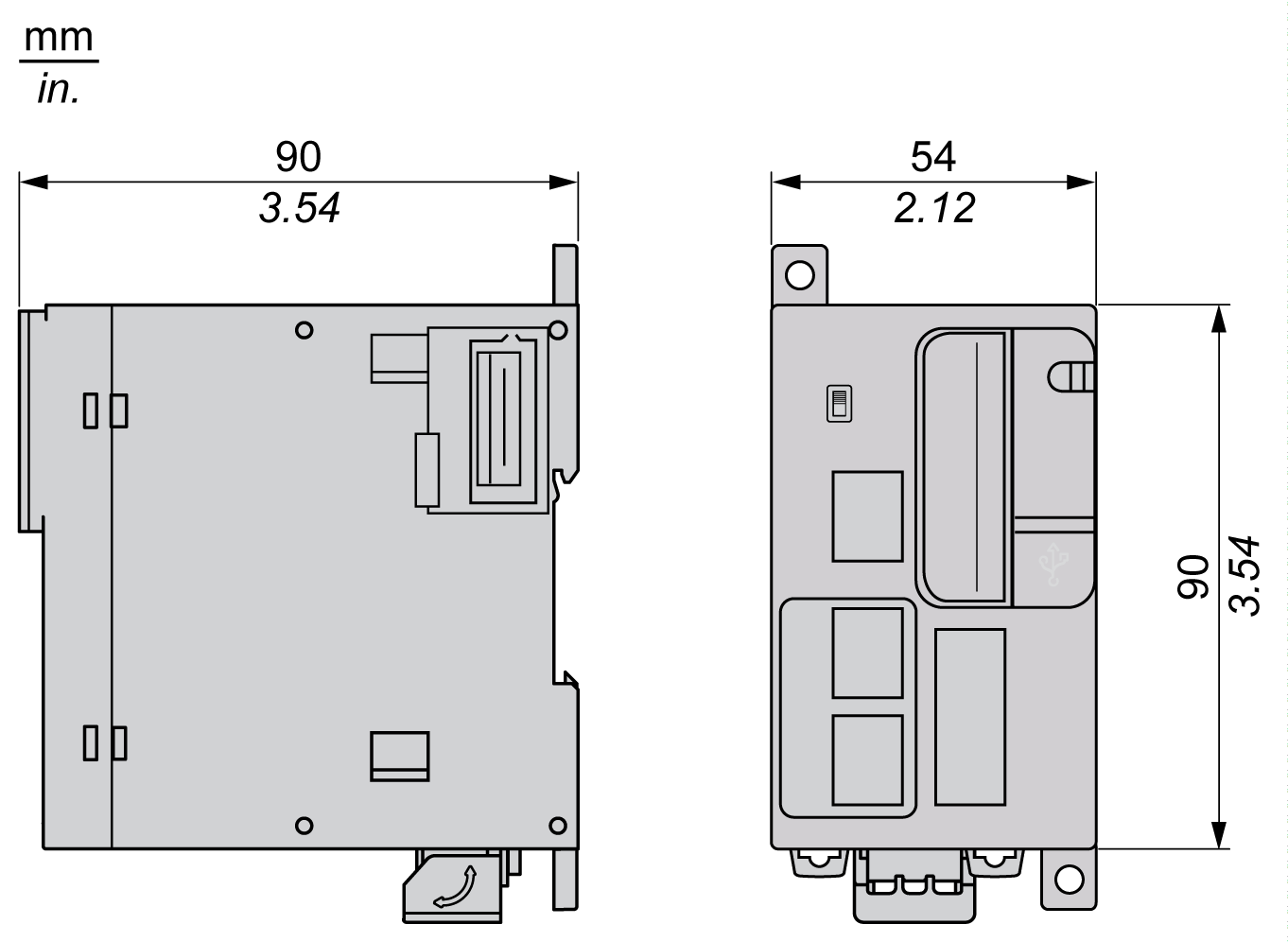
This figures shows the external dimensions of the logic controller: