Grounding the M262 Logic/Motion Controller System
Functional Ground (FE) on the DIN Rail
The DIN rail for your M262 Logic/Motion Controller controller is common with the functional ground (FE) plane and must be mounted on a conductive backplane.
|
|
|
UNINTENDED EQUIPMENT OPERATION |
|
Connect the DIN rail to the functional ground (FE) of your installation. |
|
Failure to follow these instructions can result in death, serious injury, or equipment damage. |
The connection between the functional ground (FE) and the M262 Logic/Motion Controller system is made by the DIN rail contacts on the back of the controller and the expansion modules.
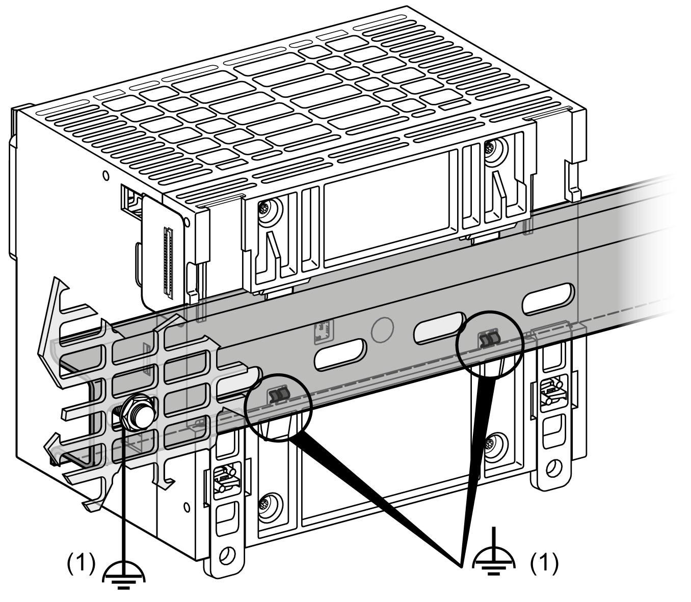
1 Functional Ground (FE)
NOTE: When the M262 Logic/Motion Controller system is mounted on a DIN rail, the Functional Ground (FE) connector on the front face of the controller can be used to help minimize electromagnetic interference:
Protective Ground (PE) on the Mounting Panel
The protective ground (PE) should be connected to the conductive mounting panel by a heavy-duty wire, usually a braided copper cable with the maximum allowable cable section.
Functional Ground (FE) on the Mounting Panel
Use a functional ground cable to connect the functional ground connector to the conductive backplane:
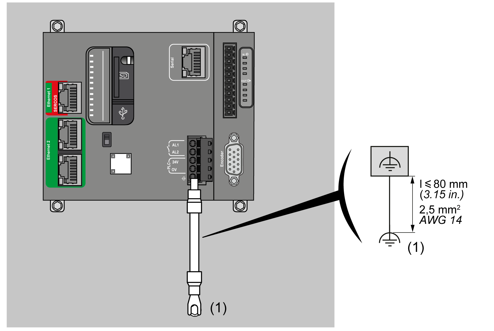
(1) Functional ground (FE)
The functional ground cable requires a cross-section of at least 1.5 mm2 (AWG 16) and a maximum length of 80 mm (3.15 in.).
To help minimize the effects of electromagnetic interference, cables carrying fieldbus communication signals must be shielded.
|
|
|
UNINTENDED EQUIPMENT OPERATION |
|
oUse shielded cables for communication signals. oGround cable shields for communication signals at a single point 1. oAlways comply with local wiring requirements regarding grounding of cable shields. |
|
Failure to follow these instructions can result in death, serious injury, or equipment damage. |
1Multipoint grounding is permissible if connections are made to an equipotential ground plane dimensioned to help avoid cable shield damage in the event of power system short-circuit currents.
The use of shielded cables requires compliance with the following wiring rules:
oFor protective ground connections (PE), metal conduit or ducting can be used for part of the shielding length, provided there is no break in the continuity of the ground connections. For functional ground (FE), the shielding is intended to attenuate electromagnetic interference and the shielding must be continuous for the length of the cable. If the purpose is both functional and protective, as is often the case for communication cables, the cable must have continuous shielding.
oWherever possible, keep cables carrying one type of signal separate from the cables carrying other types of signals or power.
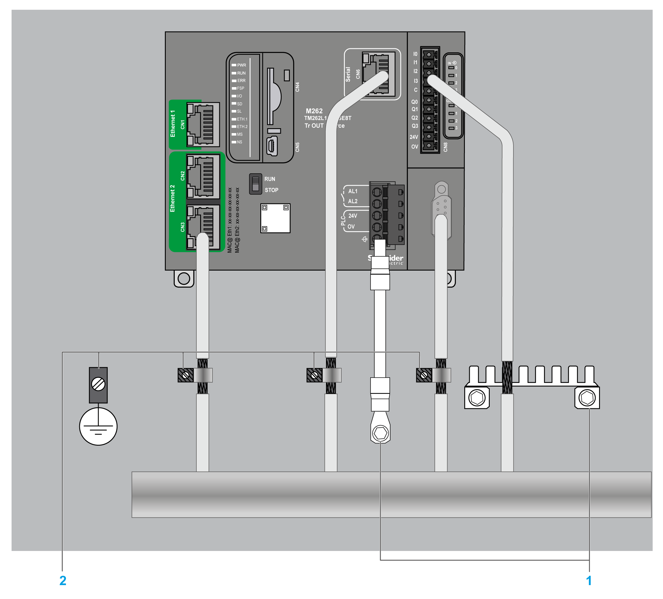
The shielding must be securely connected to ground. The fieldbus communication cable shields must be connected to the protective ground (PE) with a connecting clamp secured to the conductive backplane of your installation.
The shielding of the following cables must be connected to the protective ground (PE):
oEthernet (unless forbidden by an applicable standard)
oSerial
oEncoder (on TM262M• references)
The embedded I/O shields can be connected to either the protective ground (PE) or the functional ground (FE).
|
|
|
HAZARD OF ELECTRIC SHOCK |
|
oThe grounding terminal connection (PE) must be used to provide a protective ground at all times. oMake sure that an appropriate, braided ground cable is attached to the PE/PG ground terminal before connecting or disconnecting the network cable to the equipment. |
|
Failure to follow these instructions will result in death or serious injury. |
|
|
|
ACCIDENTAL DISCONNECTION FROM PROTECTIVE GROUND (PE) |
|
oDo not use the TM2XMTGB Grounding Plate to provide a protective ground (PE). oUse the TM2XMTGB Grounding Plate only to provide a functional ground (FE). |
|
Failure to follow these instructions can result in death, serious injury, or equipment damage. |
The figure below represents an M262 Logic/Motion Controller with shielded cables connected to a DIN rail:
1 Functional ground (FE)
2 Protective ground (PE)
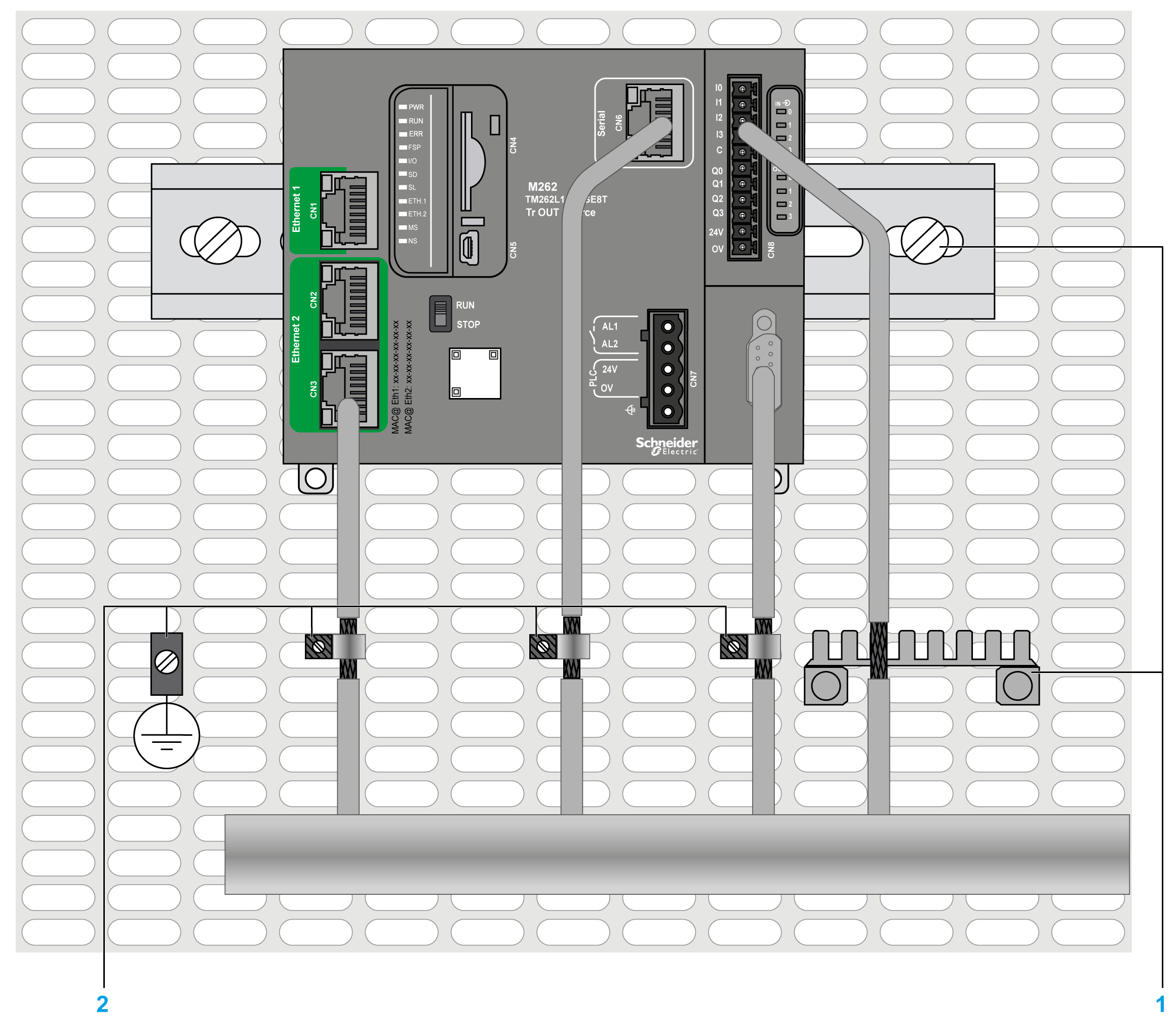
The figure below represents an M262 Logic/Motion Controller with shielded cables connected to a mounting panel:
1 Functional ground (FE)
2 Protective ground (PE)
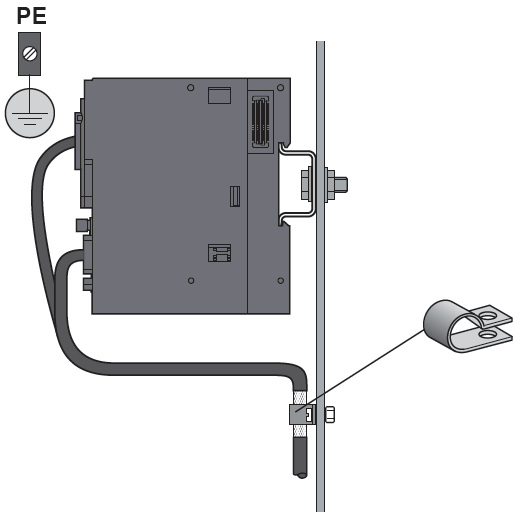
Protective Ground (PE) Cable Shielding
To ground the shield of a cable via a grounding clamp:
|
Step |
Description |
|
|---|---|---|
|
1 |
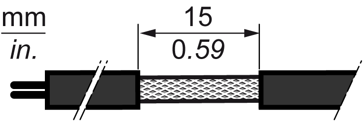
Strip the shielding for a length of 15 mm (0.59 in.) |
|
|
2 |
Attach the cable to the conductive backplane plate by attaching the grounding clamp to the stripped part of the shielding as close as possible to the base of the M262 Logic/Motion Controller. |
|
NOTE: The shielding must be clamped securely to the conductive backplane to help ensure good contact.
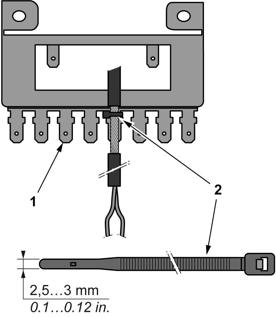
Functional Ground (FE) Cable Shielding
Connect the shield of a cable via the grounding bar:
|
Step |
Description |
|
|---|---|---|
|
1 |
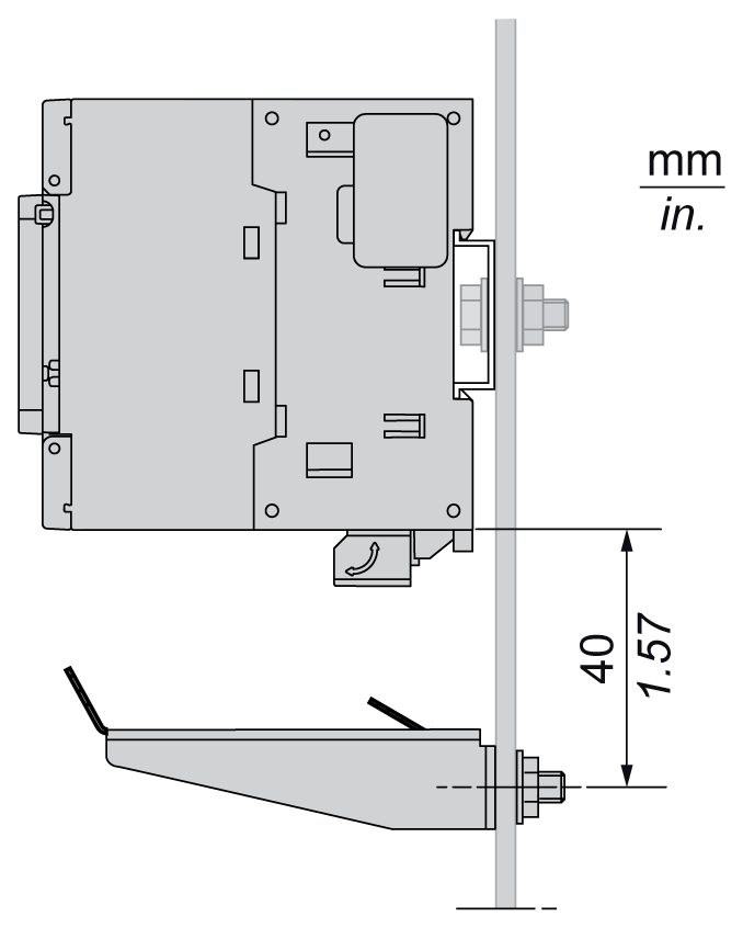
Install the TM2XMTGB grounding bar directly on the conductive backplane below the M262 Logic/Motion Controller as illustrated. |
|
|
2 |
Strip the shielding for a length of 15 mm (0.59 in.) |
|
|
3 |
Tightly clamp on the blade connector (1) using a nylon fastener (2) (width 2.5...3 mm (0.1...0.12 in.)) and appropriate tool. |
|


