The following procedures describe how to remove a TM5 System or part of a system from the DIN rail.
NOTE: When replacing a controller, a Sercos III Bus Interface or expansion modules and their bus bases, be sure to remove all power before attempting these procedures.
|
|
|
HAZARD OF ELECTRIC SHOCK, EXPLOSION OR ARC FLASH |
|
oDisconnect all power from all equipment including connected devices prior to removing any covers or doors, or installing or removing any accessories, hardware, cables, or wires except under the specific conditions specified in the appropriate hardware guide for this equipment. oAlways use a properly rated voltage sensing device to confirm the power is off where and when indicated. oReplace and secure all covers, accessories, hardware, cables, and wires and confirm that a proper ground connection exists before applying power to the unit. oUse only the specified voltage when operating this equipment and any associated products. |
|
Failure to follow these instructions will result in death or serious injury. |
Complete Configuration Removal
The following procedure describes how to remove a complete configuration:
|
Step |
Action |
|
|---|---|---|
|
1 |
Remove all power from all equipment. |
|
|
2 |
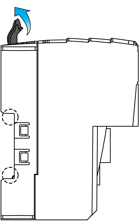
Push all the locking levers all the way up. This opens the locking mechanism for equipment installation. |

|
|
3 |
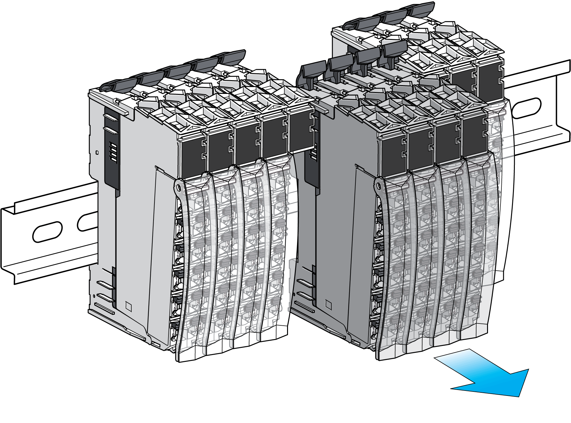
Remove the TM5 System configuration from the mounting rail. |
|
|
Step |
Action |
|
|---|---|---|
|
1 |
Remove all power from all equipment. |
|
|
2 |
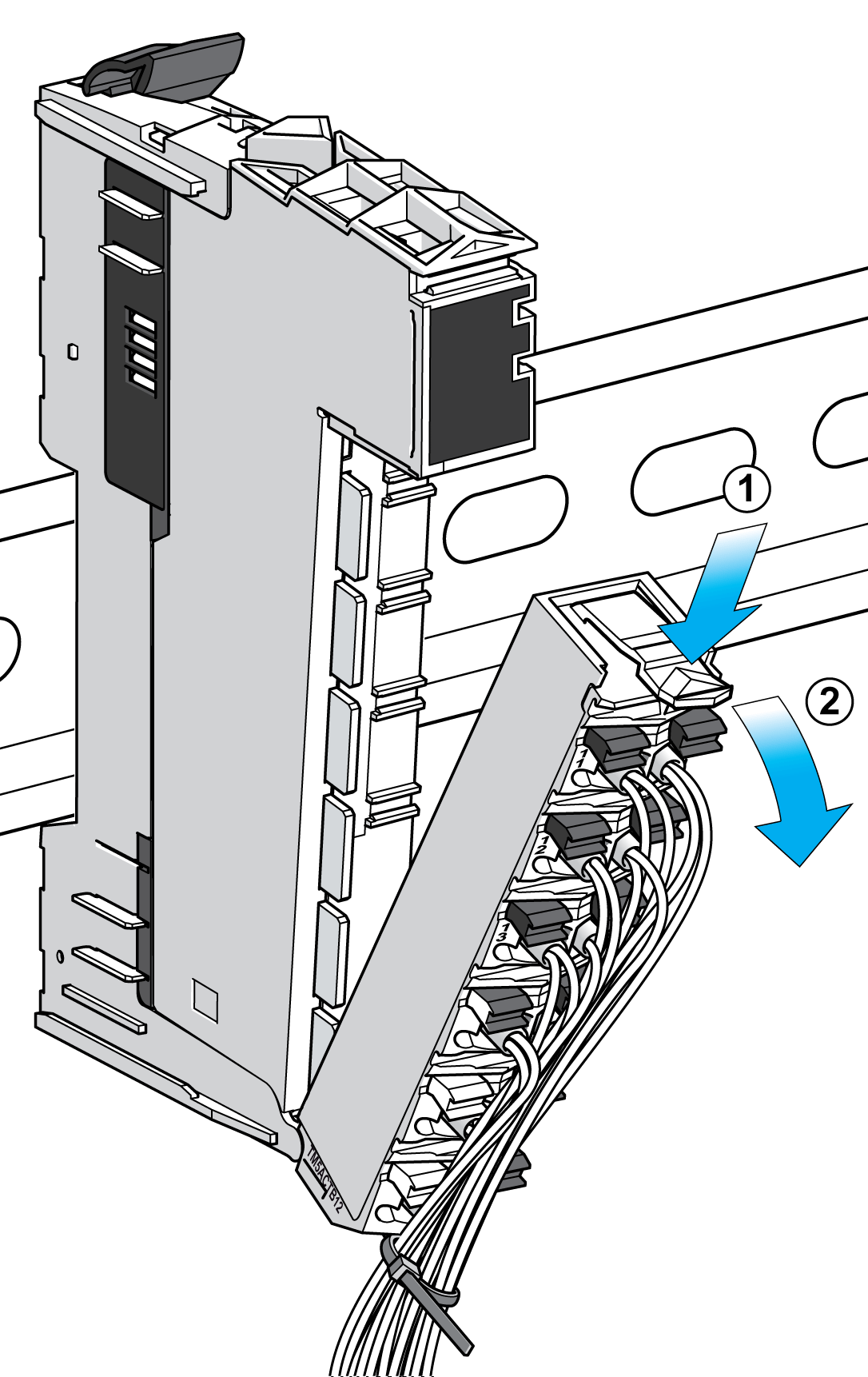
For mechanical reasons, remove the terminal block of the electronic module at the left of the partial configuration to be removed. To do this: 1 push down on the locking lever on the terminal block 2 rotate the terminal block out and down |

|
|
3 |
Push the locking levers of the configuration to be removed all the way up. This opens the locking mechanism for equipment installation. |

|
|
4 |
Remove the partial configuration from the mounting rail. 
|
|
|
5 |
Put the removed terminal block back on the electronic module. |
|