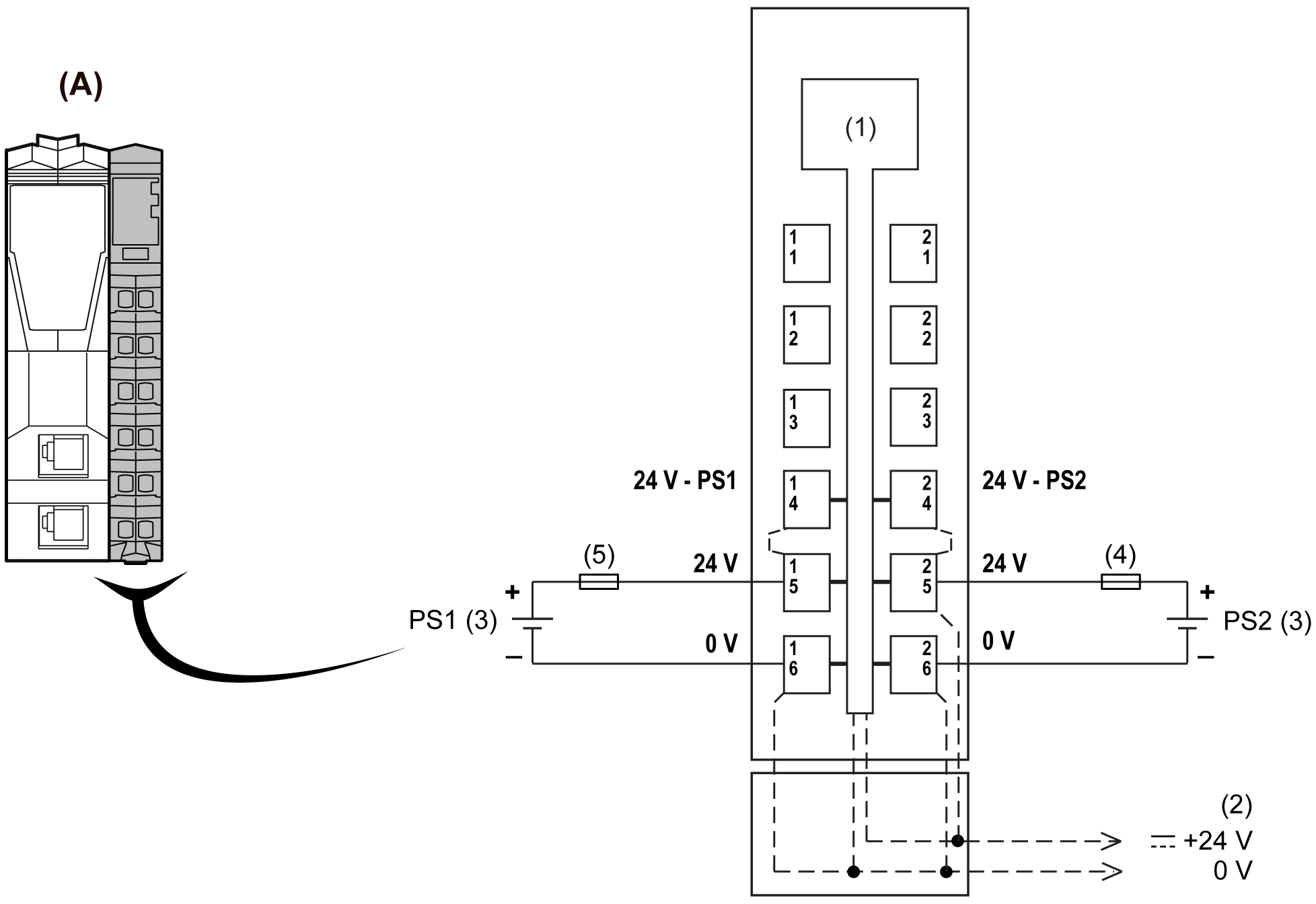
The following figure shows the wiring diagram for the Interface Power Distribution Module (IPDM) TM5SPS3:

A Interface Power Distribution Module (IPDM)
1 Internal electronics
2 24 Vdc I/O power segment integrated in the bus bases
3 PS1/PS2: External isolated power supply 24 Vdc
4 External fuse, Type T slow blow, 10 A maximum, 250 V
5 External fuse, Type T slow blow, 1 A, 250 V
NOTE: Connect the 0 Vdc power circuits together and to the functional ground (FE) of your system to meet the EMC requirements.
|
|
|
HAZARD OF ELECTRIC SHOCK, EXPLOSION, OVERHEATING AND FIRE |
|
oDo not connect the modules directly to line voltage. oUse only isolating PELV systems according to IEC 61140 to supply power to the modules. oConnect the 0 Vdc of the external power supplies to FE (Functional Earth/ground). |
|
Failure to follow these instructions will result in death or serious injury. |
|
|
|
UNINTENDED EQUIPMENT OPERATION |
|
Do not connect wires to unused terminals and/or terminals indicated as “No Connection (N.C.)”. |
|
Failure to follow these instructions can result in death, serious injury, or equipment damage. |