TM5 Safety-Related System Bus Base
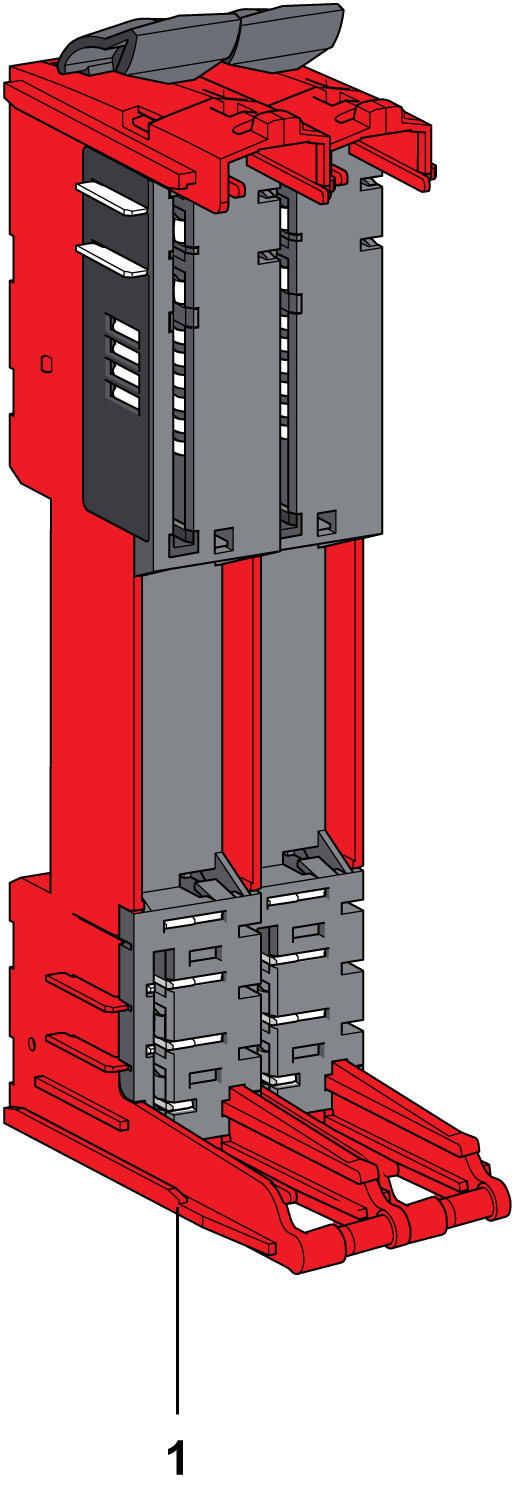
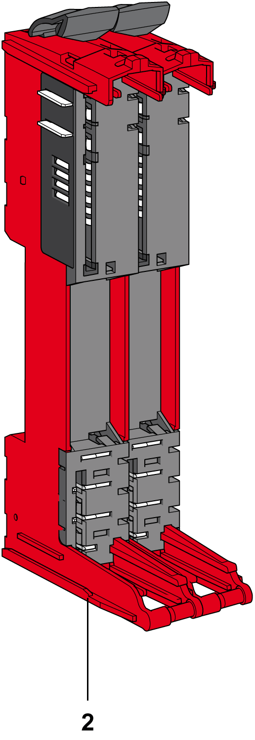
The TM5ACBM3FS red bus base is designed for 24 Vdc safety-related electronic modules.
The following figures show the TM5 Safety-Related System bus bases:
|
TM5ACBM3FS |
TM5ACBM4FS |
|---|---|

|

|
|
Number |
Reference |
Description |
Color |
|---|---|---|---|
|
1 |
TM5ACBM3FS |
Bus base 24 Vdc for safety-related modules, safety coded 24 Vdc I/O power segment pass-through |
Red |
|
2 |
TM5ACBM4FS |
Bus base 24 Vdc for safety-related modules, safety coded 24 Vdc I/O power segment left isolated |
Red |
A slice must only be composed of a single color. For example, a gray bus base should only be assembled with a gray electronic module and a gray terminal block. However, color alone is not sufficient for compatibility; always confirm that functionality of slice components matches as well.
|
|
|
INCOMPATIBLE COMPONENTS CAUSE ELECTRIC SHOCK OR ARC FLASH |
|
oDo not associate components of a slice that have different colors. oAlways confirm the compatibility of slice components and modules before installation using the association table in this manual. oVerify that correct terminal blocks (minimally, matching colors and correct number of terminals) are installed on the appropriate electronic modules. |
|
Failure to follow these instructions will result in death or serious injury. |
This section gives the TM5 System bus bases characteristics. See also environmental characteristics.
|
|
|
UNINTENDED EQUIPMENT OPERATION |
|
Do not exceed any of the rated values specified in the environmental and electrical characteristics tables. |
|
Failure to follow these instructions can result in death, serious injury, or equipment damage. |
The following table shows the technical data for TM5 System bus bases:
|
General Characteristics |
|
|---|---|
|
TM5 power bus current draw |
26 mA |
|
Power dissipation |
0.13 W maximum |