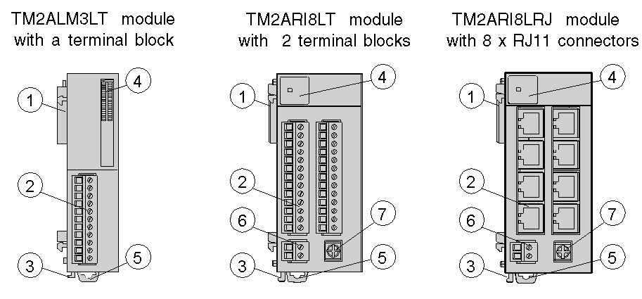
This section describes the parts of Analog I/O modules, two with terminal block and one with 8 x RJ11 connectors. Your I/O module may differ from the illustrations but the parts will be the same.

The following table describes the different elements of Analog I/O modules shown above:
|
Label |
TM2ALM3LT |
TM2ARI8LT |
TM2ARI8LRJ |
|---|---|---|---|
|
1 |
Expansion connector for electrical connection (one on each side, right side not visible). It is designed to provide continuity of the electrical link between the modules connected. |
||
|
2 |
Terminal block (supplied with the module) |
2 x Terminal block (supplied with the module) |
8 x RJ11 Connectors |
|
3 |
Locking device for attachment to the previous module |
||
|
4 |
LEDs for displaying the channels and module diagnostics |
||
|
5 |
Clip-on lock |
||
|
6 |
- |
Power supply screw terminal block: 24 Vdc |
|
|
7 |
- |
Screw for functional ground |
|