TM3TI8T / TM3TI8TG Characteristics
This section provides a description of the electrical and input/output characteristics of the TM3TI8T / TM3TI8TG expansion modules.
See also Environmental Characteristics.
|
|
|
UNINTENDED EQUIPMENT OPERATION |
|
Do not exceed any of the rated values specified in the environmental and electrical characteristics tables. |
|
Failure to follow these instructions can result in death, serious injury, or equipment damage. |
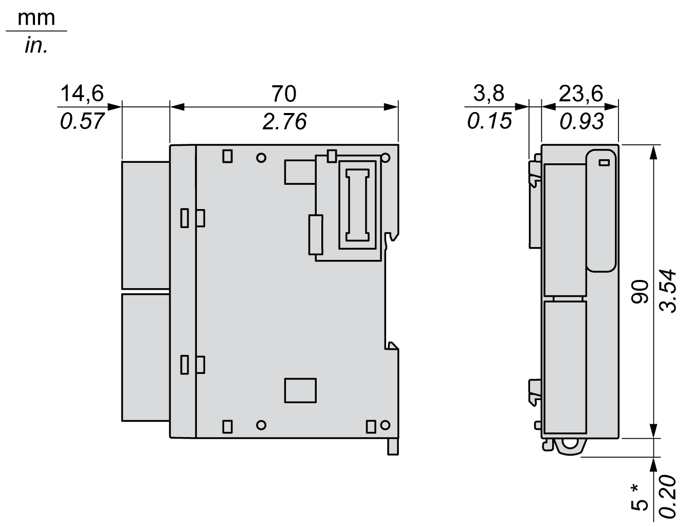
The following diagrams show the external dimensions for the TM3TI8T / TM3TI8TG expansion modules:

NOTE: * 8.5 mm (0.33 in) when the clamp is pulled out.
|
Characteristics |
Value |
|---|---|
|
Rated power supply voltage |
24 Vdc |
|
Power supply range |
20.4...28.8 Vdc |
|
Connector insertion/removal durability |
100 times minimum |
|
Current draw on 5 Vdc internal bus |
30 mA (no load) 30 mA (full load) |
|
Current draw on 24 Vdc internal bus |
0 mA |
|
Current draw on external 24 Vdc |
30 mA (no load) 30 mA (full load) |
The following table describes the input characteristics of the TM3TI8T / TM3TI8TG expansion modules:
|
Characteristics |
Value |
||||||
|---|---|---|---|---|---|---|---|
|
Thermocouple type |
Thermistor |
Resistor |
|||||
|
Input range |
K |
–200...1300 °C (–328...2372 °F) |
NTC |
Measured resistor range: 100 Ω...200 kΩ Calculated temperature range: –90...150 °C (–130...302 °F) |
100 Ω...32 kΩ |
||
|
J |
–200...1000 °C (–328...1832 °F) |
||||||
|
R |
0...1760 °C (32...3200 °F) |
||||||
|
S |
0...1760 °C (32...3200 °F) |
||||||
|
B |
0...1820 °C (32...3308 °F) |
||||||
|
E |
–200...800 °C (–328...1472 °F) |
PTC |
100 Ω...10 kΩ |
||||
|
T |
–200...400 °C (–328...752 °F) |
||||||
|
N |
–200...1300 °C (–328...2372 °F) |
||||||
|
C |
0...2315 °C (32...4199 °F) |
||||||
|
Input impedance |
1 MΩ min |
1 MΩ min |
|||||
|
Sample duration time |
100 ms per enabled channel |
||||||
|
Input type |
Single-ended input. Use only isolated thermocouples. All the shields of the sensor cables must be referenced to the logic controller ground. |
||||||
|
Operating mode |
Self-scan |
||||||
|
Conversion mode |
Sigma delta ADC |
||||||
|
Max accuracy at ambient 25 °C (77 °F) |
±0.2 % of full scale Except: |
NTC PTC |
Value is that of the thermistor used |
– |
|||
|
R S |
±6 °C at 0...200 °C (±10.8 °F at 32...392 °F) |
||||||
|
B |
Not available at 0...300 °C (32...572 °F) |
||||||
|
K J E T N |
±0.4 % of full scale under 0 °C (32 °F) |
||||||
|
Temperature drift |
±0.01 % of full scale |
||||||
|
Repeatability after stabilization time |
±0.5 % of full scale |
||||||
|
Nonlinearity |
±0.2 % of full scale |
||||||
|
Maximum input deviation |
±1.0 % of full scale |
||||||
|
Resolution |
K J R S B E T N C |
15000 points 12000 points 17600 points 17600 points 18200 points 10000 points 6000 points 15000 points 23150 points |
NTC |
2400 points (–90...150 °C) |
31900 points (100...32000 Ω) |
||
|
PTC |
9900 points (100...10000 Ω) |
||||||
|
Input value of LSB |
0.1 °C (0.18 °F) |
NTC |
1 Ω or 0.1 °C (0.18 °F) |
– |
|||
|
PTC |
1 Ω |
||||||
|
Thermistor parameters (configuration per channel) |
– |
R: 0…65535 (1 Ω /LSB) T: 1…1000 (1 °C/LSB) B: 1…32767 (1 K/LSB) |
– |
||||
|
Data type in application program |
Scalable from –32768 to 32767 |
||||||
|
Input data out of range detection |
Yes |
||||||
|
Noise resistance |
Maximum temporary deviation during perturbations |
±4 % maximum when EMC perturbation is applied to the power and I/O wiring |
|||||
|
Cable |
Twisted-pair shielded cable |
||||||
|
Crosstalk |
1 LSB max |
||||||
|
Isolation |
Between external power supply and inputs |
1500 Vac |
|||||
|
Between inputs and internal logic circuits |
500 Vac |
||||||
|
Maximum continuous allowed overload (no damage) |
N/A |
||||||
|
Input filter |
Software filter: 0...10 s (per 0.01 s unit) |
||||||
|
Behavior when external power is off |
Input value is not relevant The external power supply error status bit in the controller is ON. |
||||||