In online mode, the Status tab of the bus coupler provides monitoring and diagnostics information for the bus coupler and connected modules.
Displaying Diagnostic Information
Bus coupler and expansion module status information is displayed under the Status tab of the bus coupler in EcoStruxure Machine Expert.
For more information, refer to Status tabs description.
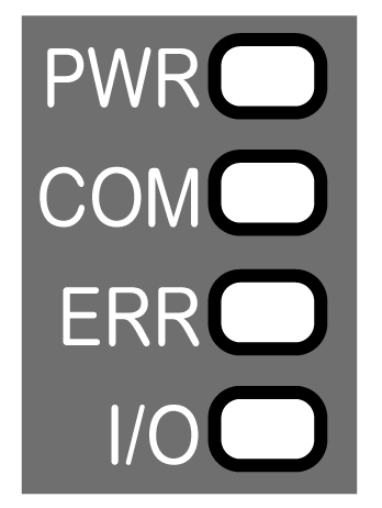
The following graphic shows the LEDs of TM3 Modbus Serial Line bus coupler:

The following table describes the status LEDs:
|
LED |
Color |
Status |
Description |
|---|---|---|---|
|
PWR |
Green |
On |
Power is applied. |
|
Off |
Power is removed. All LED indicators are off. |
||
|
COM |
Green |
Flashing |
Data sending and receiving. |
|
Off |
No data exchanged. |
||
|
Red |
Flashing |
Device is receiving an incorrect data frame. |
|
|
ERR |
Red |
Flashing |
Device has detected an error that is, under most circumstances, recoverable. For example: oRotary switch position changed during operational mode. Return to the initial position to reset the LED behavior. oError detected during firmware update. oCommunication and configuration errors. |
|
Off |
No error detected. |
||
|
I/O |
Green |
Flashing |
Device has received and applied the expansion modules configuration. |
|
On |
Device is communicating with the expansion modules. |
||
|
Green Red |
Flashing On |
The physical configuration is inconsistent with the software configuration. No data exchange (status and I/O) is occurring. |
|
|
Green Red |
On On |
The physical configuration is inconsistent with the software configuration. I/O data is not applied. |
|
|
Green Red |
On Flashing |
At least one TM2 or TM3 expansion module did not respond to the bus coupler for 10 consecutive cycles. |
|
|
Off |
No configuration. Device is not communicating with the expansion modules. |
NOTE: With the exception of the PWR LED, each LED is ON for a few seconds, then OFF during boot sequence. The LED behavior rules apply when the boot is completed successfully.
Serial Line Bus Coupler Status Diagnostics
The following table provides detailed information regarding the bus coupler status, expansion module status as well as communication statistics:
|
Register |
Function |
Bit |
Description |
|---|---|---|---|
|
900 |
Bus status |
0…8 |
Reserved |
|
9 |
Communication error or external error |
||
|
10…12 |
Reserved |
||
|
13 |
Expansion modules missing or incorrectly configured |
||
|
14…15 |
Reserved |
||
|
901 |
Expansions error |
0 |
Module 1 error |
|
1 |
Module 2 error |
||
|
2 |
Module 3 error |
||
|
3 |
Module 4 error |
||
|
4 |
Module 5 error |
||
|
5 |
Module 6 error |
||
|
6 |
Module 7 error |
||
|
7 |
Module 8 error |
||
|
8 |
Module9 error |
||
|
9 |
Module 10 error |
||
|
10 |
Module 11 error |
||
|
11 |
Module 12 error |
||
|
12 |
Module 13 error |
||
|
13 |
Module 14 error |
||
|
14…15 |
Reserved |
||
|
902 - 929 |
Reserved |
- |
Reserved |
|
930 |
TM2/TM3 bus status |
0…1 Module 1 |
Module status (2 bits per module): o0x0: Module OK o0x1: Module configuration error detected o0x2: Module runtime error detected o0x3: Module not present but it is optional module |
|
2…3 Module 2 |
|||
|
4…5 Module 3 |
|||
|
6…7 Module 4 |
|||
|
8…9 Module 5 |
|||
|
10…11 Module 6 |
|||
|
12…13 Module 7 |
|||
|
14…15 Module 8 |
|||
|
931 |
TM2/TM3 bus status |
0…1 Module 9 |
Module status (2 bits per module): o0x0: Module OK o0x1: Module configuration error detected o0x2: Module runtime error detected o0x3: Module not present but it is optional module |
|
2…3 Module 10 |
|||
|
4…5 Module 11 |
|||
|
6…7 Module 12 |
|||
|
8…9 Module 13 |
|||
|
10…11 Module 14 |
|||
|
12…13 |
Reserved |
||
|
14…15 |
Bus status: o0x0: Bus OK o0x1: Bus configuration error detected o0x2: Bus runtime error detected o0x3: Bus not configured |
||
|
932 |
System State |
– |
o0x0: System is booting. o0x1: TM3 bus is not configured. o0x2: A TM3 configuration is being transferred. o0x3: A valid TM3 configuration has been applied successfully. o0x4: TM3 bus is controlled by Modbus SL IOScanner. o0x5: TM3 bus is controlled by Web server. o0x6: Timeout on fieldbus refresh o0x7: Firmware update in progress o0x9: System state transition in progress. |
Serial Line Bus Coupler Communication Diagnostics
The following table provides information regarding the registers for communication management:
|
Register |
Function |
Description |
|---|---|---|
|
990 |
Not used |
– |
|
991 |
Number of received messages |
Number of messages received |
|
992 |
Number of sent messages |
Number of messages sent |
|
993 |
Number of non-valid messages |
Number of corrupted messages (format error in the request, invalid action or CRC) |