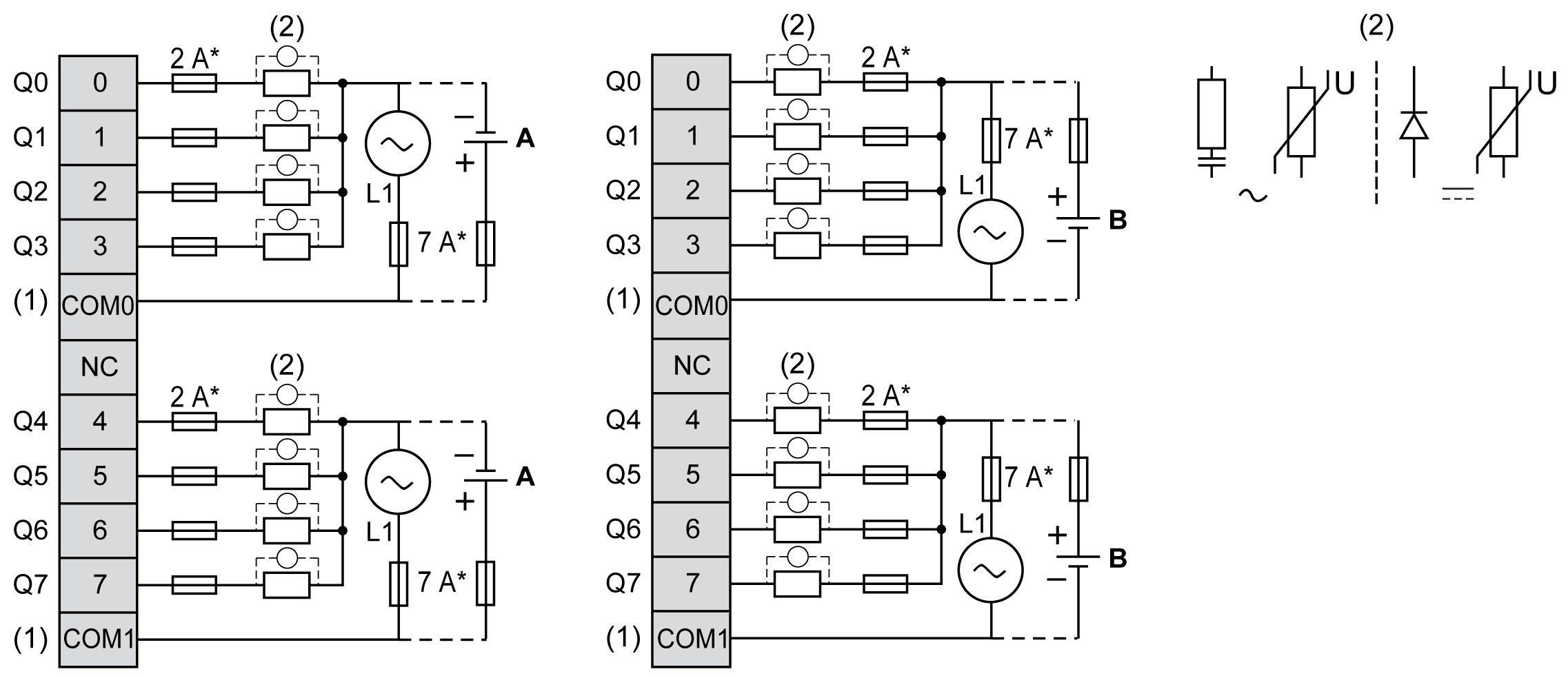
TM3DQ8R / TM3DQ8RG Wiring Diagram
These expansion modules have a built-in removable screw or spring terminal block for the connection of outputs and power supply.
The following figure illustrates the connections between the outputs, the actuators, and their commons:

* Type T fuse
(1) The COM0 and COM1 terminals are not connected internally
(2) To improve the life time of the contacts, and to protect from potential inductive load damage, connect a free wheeling diode in parallel to each inductive DC load or an RC snubber in parallel of each inductive AC load, or a varistor on either type of load.
A Source wiring (positive logic)
B Sink wiring (negative logic)
NOTE: When you use the TM3 expansion module with a TM3 Ethernet bus coupler, you must connect an RC snubber in parallel of each inductive AC load.
For information about 24 Vdc power supply, refer to DC Power Supply Characteristics.
|
|
|
UNINTENDED EQUIPMENT OPERATION |
|
Do not connect wires to unused terminals and/or terminals indicated as “No Connection (N.C.)”. |
|
Failure to follow these instructions can result in death, serious injury, or equipment damage. |