TM3XFHSC202 / TM3XFHSC202G Characteristics
This section provides a description of the characteristics of the TM3XFHSC202 / TM3XFHSC202G modules. See also Environmental Characteristics.
|
|
|
UNINTENDED EQUIPMENT OPERATION |
|
Do not exceed any of the rated values specified in the environmental and electrical characteristics tables. |
|
Failure to follow these instructions can result in death, serious injury, or equipment damage. |
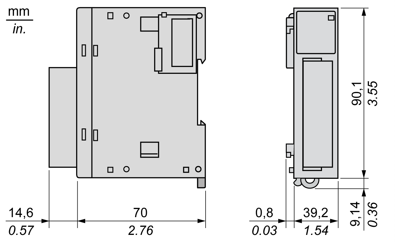
The following diagram shows the dimensions of the TM3XFHSC202 / TM3XFHSC202G modules:

|
Characteristics |
Value |
|---|---|
|
Rated power supply voltage |
24 Vdc |
|
Voltage limit |
20.4...28.8 Vdc |
|
Current draw on 5 Vdc internal bus |
Typically 65 mA at 25°C (77°F), maximum 110 mA |
|
Current draw on 24 Vdc internal bus |
Typically 30 mA at 25°C (77°F), maximum 50 mA |
|
Isolation between input and internal logic |
550 Vac for 1 min |
|
Isolation between output and internal logic |
550 Vac for 1 min |
|
Connection type |
TM3XFHSC202 / TM3XHSC202: Removable screw terminal block TM3XFHSC202G / TM3XHSC202G: Removable spring terminal block |
|
Connector insertion/removal durability |
Over 100 times |
|
Weight |
120 g without terminal block 150 g with terminal block |
|
Characteristics |
Value |
|
|---|---|---|
|
Number |
10 |
|
|
Number of channel groups |
2 channel groups: 1 common line for I0 ...I4 1 common line for I5 ...I9 |
|
|
Input type |
Type 1 (IEC 61131-2) |
|
|
Logic type |
Sink |
|
|
Rated input voltage |
24 Vdc |
|
|
Input voltage limit |
Maximum 30 Vdc |
|
|
Rated input current |
7.5 mA |
|
|
Input impedance |
2.81 kΩ |
|
|
Input limit values |
Voltage at state 1 |
> 15 Vdc (15...28.8 Vdc) |
|
Voltage at state 0 |
< 5 Vdc (0...5 Vdc) |
|
|
Current at state 1 |
> 3 mA |
|
|
Current at state 0 |
< 1.5 mA |
|
|
Turn on time |
< 1 µs + filter delay |
|
|
Turn off time |
< 1 µs + filter delay |
|
|
Maximum input frequency |
200 kHz |
|
|
Isolation |
Between input and internal logic |
550 Vac for 1 minute |
|
Between input groups |
None |
|
|
Between input channels |
None |
|
|
Between inputs and outputs |
550 Vac for 1 minute |
|
|
Cable type |
Shielded cable, including the COM signal Length: Maximum 10 m |
|
|
Characteristics |
Value |
|---|---|
|
Number |
8 |
|
Number of channel groups |
2 channel groups: Q0...Q3 Q4...Q7 |
|
Output type |
Transistor |
|
Logic type |
Source (push-pull) |
|
Rated output voltage |
24 Vdc |
|
Rated output current |
300 mA |
|
Total rated output current per group |
Maximum 1.2 A |
|
Maximum power of filament lamp |
Maximum 0.9 W |
|
Leakage current |
≤ 0.15 mA |
|
Turn on time |
Maximum 1 µs |
|
Turn off time |
Maximum 1 µs |
|
Protection against short circuit or overload |
Yes, typically 1 A per output Defect managed by group: oQ0...Q3 oQ4...Q7 |
|
Automatic rearming after short circuit or overload |
Yes, 10 s Enabled/Disabled by EcoStruxure Machine Expert |
|
Clamping voltage |
Typically 45 Vdc |
|
Isolation |
Between outputs and internal logic: 550 Vac for 1 minute |
|
Between output groups: none |
|
|
Between output channels: none |
|
|
Between outputs and inputs: 550 Vac for 1 minute |
|
|
Cable length |
< 30 m |
|
Characteristics |
Value |
|---|---|
|
Type |
PELV |
|
Voltage nominal |
24 Vdc |
|
Voltage limits |
20.4...28.8 Vdc with a maximum ripple of 10% of nominal voltage |
|
Input current |
Maximum 2.5 A |
|
Inrush current |
Not limited (except by overload peak current) |
|
Voltage drop immunity |
No |
|
Reverse polarity protection |
Yes |
|
Overvoltage protection |
No (external fuse required) |
|
Power presence detection |
Yes, threshold 15 V |
|
Isolation |
550 Vac for 1 minute with internal logic |
|
Cable length |
< 3 m |