TM3XHSC202 / TM3XHSC202G Wiring Diagram
The TM3XHSC202 / TM3XHSC202G are equipped with two removable connection screw terminal blocks for the connection of inputs and outputs.
The following diagram shows he wiring of the inputs:
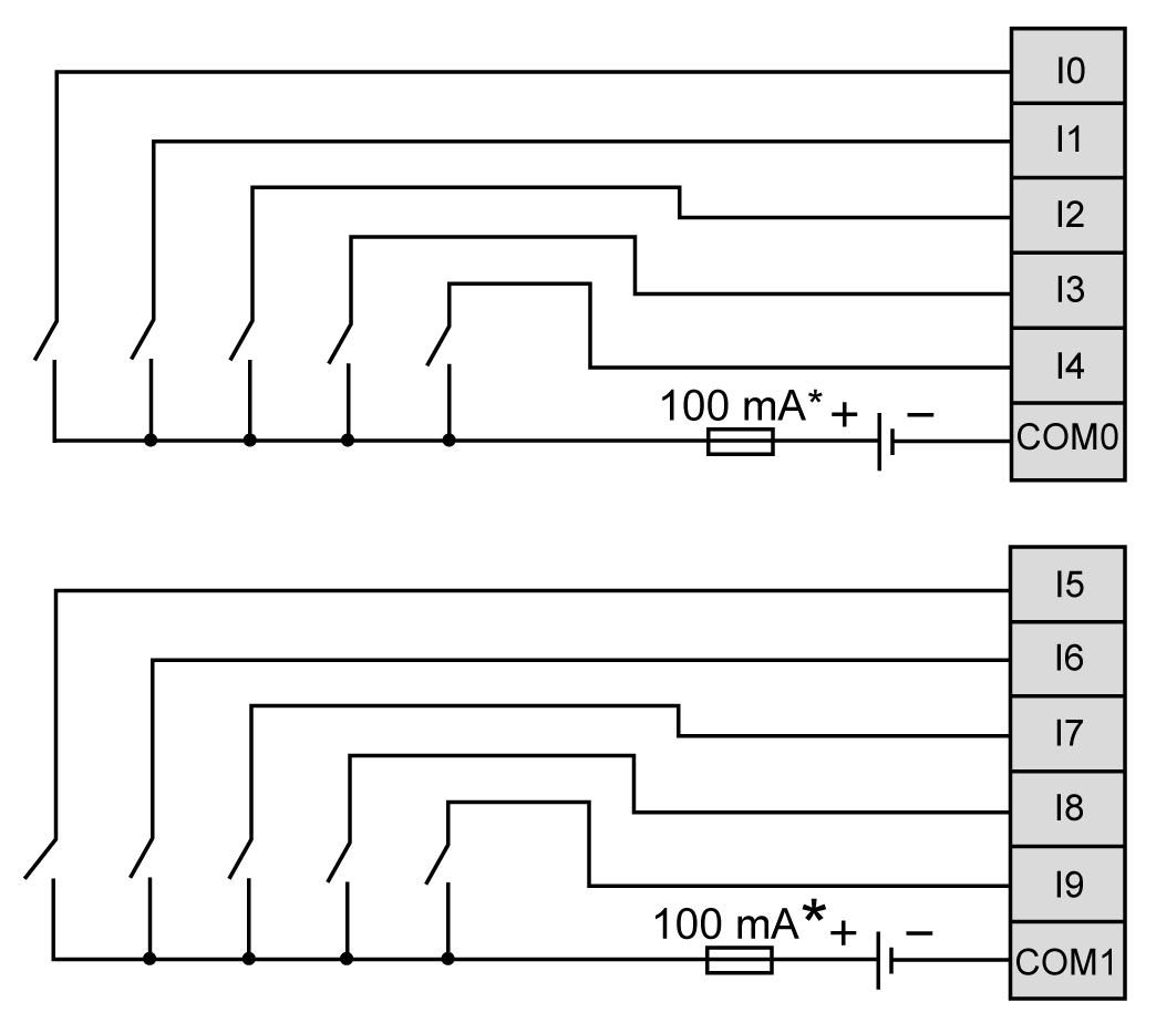
* Type T fuse
|
|
|
UNINTENDED EQUIPMENT OPERATION |
|
Ensure that the physical wiring respects the connections indicated in the wiring diagram. In particular, that the 24V terminal is connected, only 24 Vdc is connected to the 24V terminal, and only 0 Vdc is connected to the 0V terminal. |
|
Failure to follow these instructions can result in death, serious injury, or equipment damage. |
The following diagram shows the wiring of the outputs:
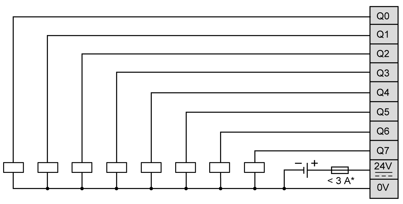
* Connect an appropriate type T fuse for the load, not to exceed 3 A.
The following diagram shows the encoder wiring:
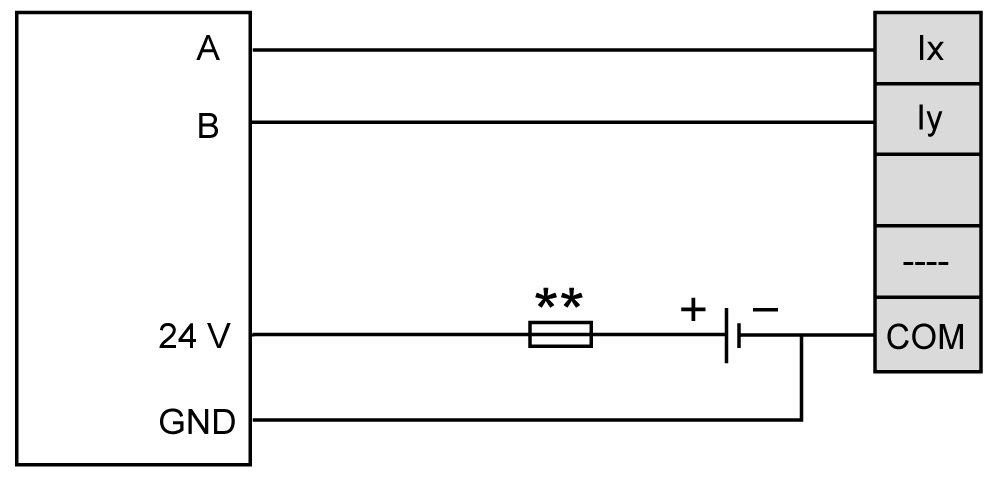
** Refer to the encoder documentation for fuse sizing
NOTE:
You must connect the output GND of the encoder to the COM terminal corresponding to the group of inputs which A and B are connected to:
oI0...I4: COM0
oI5...I9: COM1
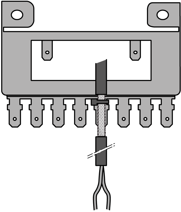
The following diagram shows how to wire the screw to the functional ground:
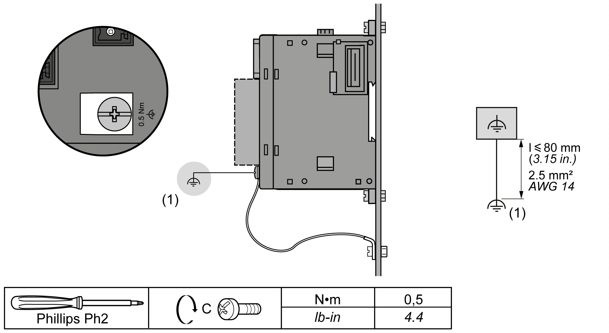
(1) Functional ground (FE)
Applying torque above the limit may damage the terminal screw or threads.
|
NOTICE |
|
INOPERABLE EQUIPMENT |
|
Do not tighten screw terminals beyond the specified maximum torque (Nm / lb-in.). |
|
Failure to follow these instructions can result in equipment damage. |
The following diagram shows how to connect the input and output cable shielding to the functional earth:
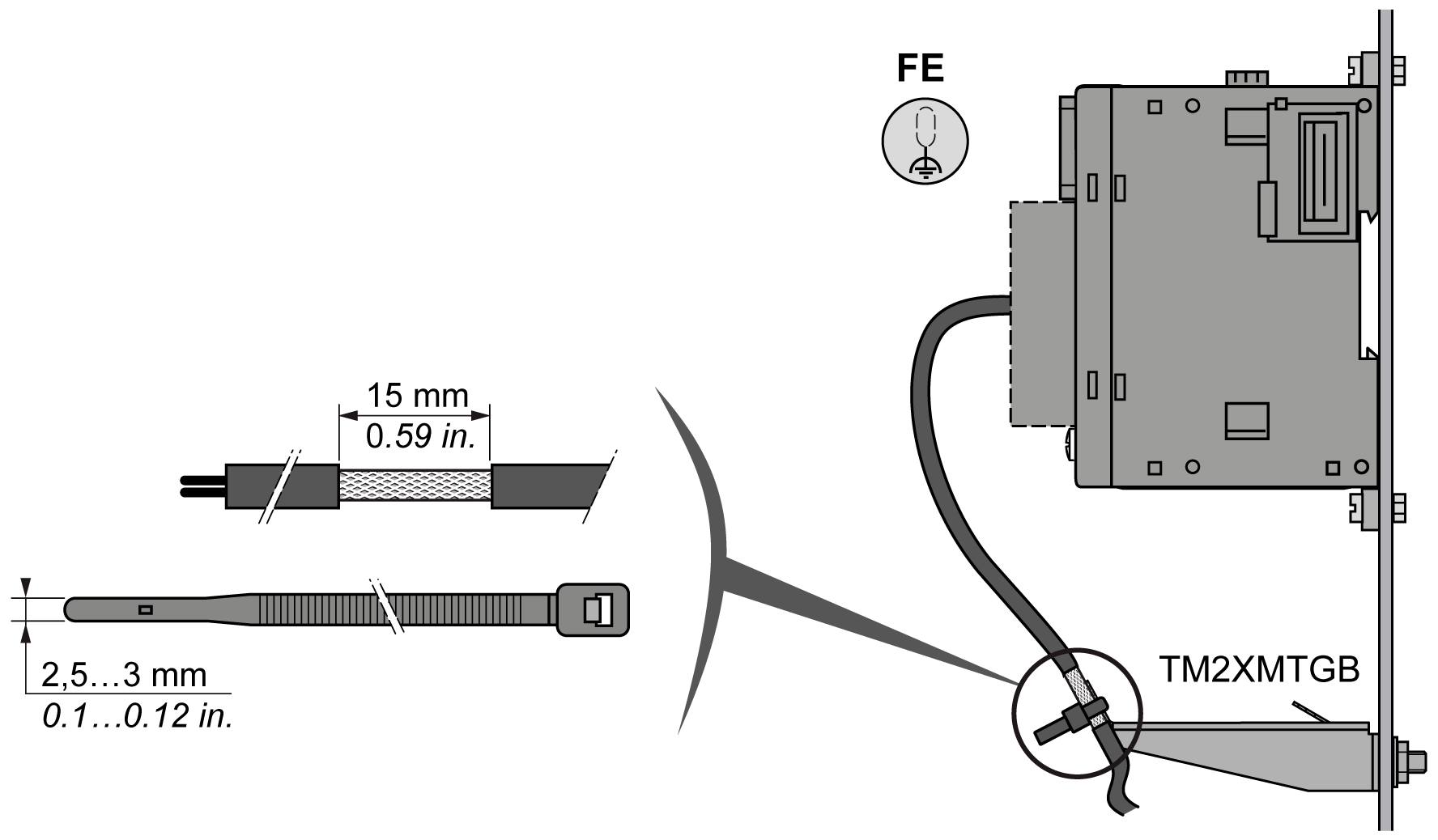
NOTE: The power supply wiring must be kept as short as possible.
