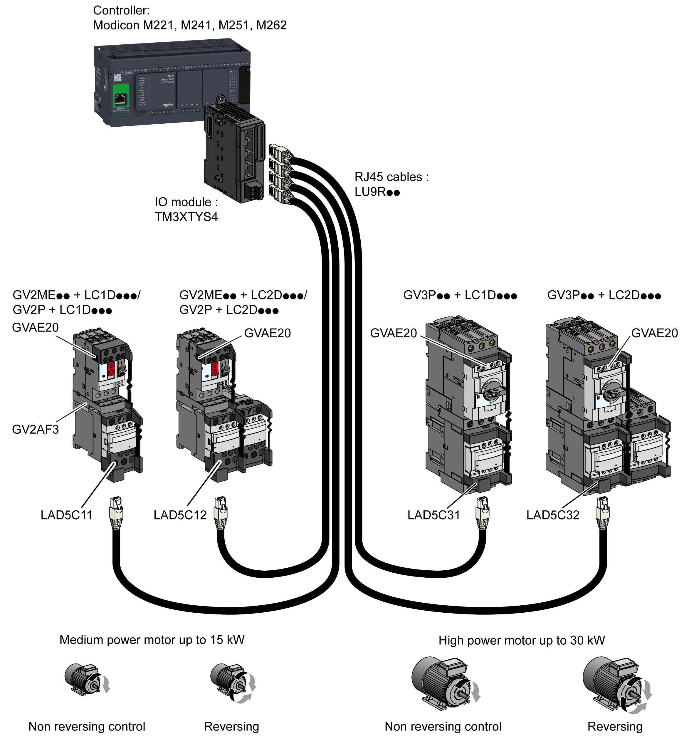
TeSys module:
o4 channels, each with
o3 sink inputs
o2 source transistor outputs
oRemovable 24 Vdc power supply terminal block
For information on the compatibility of this module, refer to EcoStruxure Machine Expert Compatibility and Migration User Guide.
The TM3XTYS4 module connects the controller to the parallel wiring system of TeSys U and/or TeSys D. This parallel wiring module provides the status and command information for each starter. One TM3XTYS4 module can manage up to 4 starters, reverse or forward, whatever they are TeSys D or TeSys U.
TM3XTYS4 module is compatible with:
oTeSys U system
oTeSys D system
TeSys U System Architecture Example
TeSys model U is an integrated modular power management system for motor starters. The system provides motor starter overload protection and control functions.
The complete TeSys model U parallel wiring system consists in:
oa power base
oa contactor
oa thermal overload protection device
oa control unit for controller-starters

TeSys D System Architecture Example
TeSys model D is a motor control interface system for motor starters. The system provides motor starter overload protection and control functions.
The complete TeSys model D parallel wiring system consists in:
oa power base
oa contactor
oa thermal overload protection device
oa control unit for controller-starters

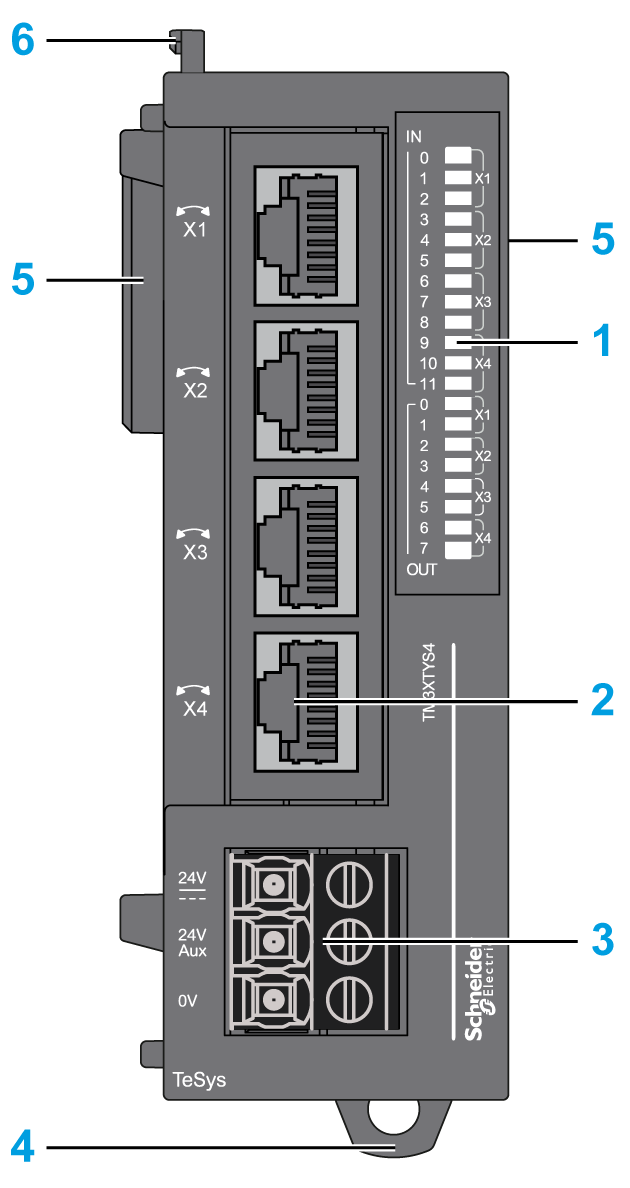
The following figure shows the main elements of the TM3XTYS4 module:

|
Label |
Elements |
Refer to |
|---|---|---|
|
1 |
LEDs for displaying the state of the I/O channel. |
– |
|
2 |
TeSys RJ45 connectors. |
– |
|
3 |
Power supply screw terminal block. |
|
|
4 |
Clip-on lock for 35 mm (1.38 in.) top hat section rail (DIN-rail). |
|
|
5 |
Expansion connector for TM3 I/O bus. |
– |
|
6 |
Locking device for attachment to the previous module. |
– |
|
Characteristics |
Value |
|
|---|---|---|
|
Input |
Input 1: Ready Input 2: Run Input 3: Trip |
|
|
Input type |
24 Vdc Type 1 (IEC/EN 61131-2) |
|
|
Logic type |
Sink |
|
|
Output |
Output 1: Direction 1 control Output 2: Direction 2 control |
|
|
Output type |
24 Vdc / 0.3 A |
|
|
Logic type |
Source |
|
|
Cable types and weight |
||
|
Cable type and length |
Type |
Ethernet CAT 5E |
|
Length |
Max. 5 m (16.4 ft) |
|
|
Weight |
115 g (4 oz) |
|
The following figure shows the status LEDs:

The following table describes the status LEDs:
|
LED |
Color |
Status |
Type |
Description |
|---|---|---|---|---|
|
X1 (0...2) |
Green |
On |
Input |
The input channel is activated |
|
Off |
The input channel is deactivated |
|||
|
X2 (3...5) |
On |
The input channel is activated |
||
|
Off |
The input channel is deactivated |
|||
|
X3 (6...8) |
On |
The input channel is activated |
||
|
Off |
The input channel is deactivated |
|||
|
X4 (9...11) |
On |
The input channel is activated |
||
|
Off |
The input channel is deactivated |
|||
|
X1 (0, 1) |
On |
Output |
The output channel is activated |
|
|
Off |
The output channel is deactivated |
|||
|
X2 (2, 3) |
On |
The output channel is activated |
||
|
Off |
The output channel is deactivated |
|||
|
X3 (4, 5) |
On |
The output channel is activated |
||
|
Off |
The output channel is deactivated |
|||
|
X4 (6, 7) |
On |
The output channel is activated |
||
|
Off |
The output channel is deactivated |