HSCMain_TM3: Control a Main Type Counter for TM3
This function block controls a Main type counter with the following functions:
oup/down counting
ofrequency meter
othresholds
oevents
operiod meter
odual phase
The HSC Main function block is mandatory when using Main counter.
The function block instance name must match the name defined by configuration. Hardware related information managed by this function block is synchronized with the MAST task cycle.
|
|
|
UNINTENDED OUTPUT VALUES |
|
oOnly use the Function Block instance in the MAST task. oDo not use the same Function Block instance in a different task. |
|
Failure to follow these instructions can result in death, serious injury, or equipment damage. |
NOTE: Forcing the logical output values of the FB is allowed by EcoStruxure Machine Expert but it will have no impact on hardware related outputs if the function is active (executing).
To see the general representation in IL or ST language, refer to Function and Function Block Representation.
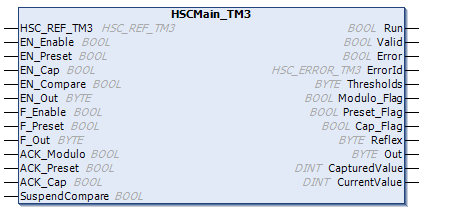
This table describes the input variables:
|
Input |
Type |
Description |
|---|---|---|
|
HSC_REF_TM3 |
HSC_REF_TM3 |
Reference to the HSC instance. |
|
EN_Enable |
BOOL |
TRUE = authorizes enabling of the counter using the Enable input. |
|
EN_Preset |
BOOL |
TRUE = authorizes counter synchronization and start using the Sync input. |
|
EN_Cap |
BOOL |
TRUE = enables the Capture input (if configured in One shot, Modulo loop, Free large modes). |
|
EN_Compare |
BOOL |
TRUE = enables the comparator operation (using Thresholds 0, 1, 2, 3): obasic comparison (TH0, TH1, TH2, TH3 output bits) oreflex (Reflex0, Reflex1, Reflex2, Reflex3 output bits) oevents (to trigger external tasks on threshold crossing) NOTE: This option is only available for TM3XF• expansion modules, which support external events. |
|
EN_Out |
BYTE |
Set bits to 1 to enable the corresponding physical outputs to echo the configured function value (Reflex or Stop) as a result of the comparison function. Only active when outputs configured in HSC editor: oBit 0: Output 0 enabled. oBit 1: Output 1 enabled. oBit 2: Output 2 enabled. oBit 3: Output 3 enabled. oBits 4...7: Not used. Association of HSC output Outx with physical output Qy is done by configuration (One-shot, Modulo loop, Free large, Period Meter Edge to Edge and Period Meter Edge to Opposite modes). |
|
F_Enable |
BOOL |
TRUE = activates counter and takes into account pulses on the counter input. |
|
F_Preset |
BOOL |
On rising edge, authorizes counting function synchronization and start in the following counting modes: One-shot counter: to preset and start the counter Modulo loop counter: to reset and start the counter Free large counter: to preset and start the counter Event counter: to restart the internal time base at the beginning Frequency meter: to restart the internal timer relative to the time base. The counter value is not preset. |
|
F_Out |
BYTE |
Set bits to 1 to force the corresponding physical outputs to 1 if associated with HSC by configuration. Takes priority over EN_Out. Only active when outputs configured in HSC editor: oBit 0: Output 0 forced. oBit 1: Output 1 forced. oBit 2: Output 2 forced. oBit 3: Output 3 forced. oBits 4...7: Not used. Association of HSC output Outx with physical output Qy is done by configuration (One-shot, Modulo loop, Free large, Period Meter Edge to Edge and Period Meter Edge to Opposite modes). |
|
ACK_Modulo |
BOOL |
On rising edge, resets Modulo_Flag (Modulo loop and Free large modes). No effect in One-shot mode. |
|
ACK_Preset |
BOOL |
On rising edge, resets Preset_Flag. Not applicable in Period Meter mode. |
|
ACK_Cap |
BOOL |
On rising edge, resets the Cap_Flag (One-shot, Modulo loop, Free large modes). |
|
SuspendCompare |
BOOL |
TRUE = compare results are suspended: oEvents are masked. NOTE: EN_Compare, EN_Reflex, F_Out remain operational while SuspendCompare is set. Not applicable in Event Counting and Frequency Meter modes. |
This table describes the output variables:
|
Outputs |
Type |
Comment |
|---|---|---|
|
Run |
BOOL |
TRUE = counter is activated. One shot mode: The Run bit is set to 0 when counter value reaches 0. A preset is needed to restart the counter. Period Meter Edge to Edge mode: The Run bit is set to 1 at rising edge detection, and reset to 0 at falling edge. Period Meter Edge to Opposite mode: The Run bit is set to 1 at first rising edge detection. It is only reset to 0 if the counter is disabled or an error is detected. |
|
Valid |
BOOL |
Set to TRUE when CurrentValue is valid. |
|
Error |
BOOL |
TRUE = indicates that an error was detected. |
|
ErrorId |
HSC_ERROR_TM3 |
Indicates the value of the error detected. See HSC_ERROR_TM3 enumeration. |
|
Thresholds |
BYTE |
Bits set to 1 when CurrentValue ≥ Threshold for corresponding threshold: oBit 0: CurrentValue ≥ Threshold 0 oBit 1: CurrentValue ≥ Threshold 1 oBit 2: CurrentValue ≥ Threshold 2 oBit 3: CurrentValue ≥ Threshold 3 oBits 4...7: Not used Not applicable in Event Counting and Frequency Meter modes. |
|
Modulo_Flag |
BOOL |
Set to TRUE when the counter rolls over its limits in the following modes: oModulo loop counter: when the counter rolls over to the modulo or 0 oFree large counter: when the counter roll overs its limits Applicable only in HSC Main Single Phase and HSC Main Dual Phase modes. |
|
Preset_Flag |
BOOL |
Set to TRUE by the synchronization of: oOne-shot counter: when the counter presets and starts oModulo loop counter: when the counter resets oFree large counter: when the counter presets oEvent counter: when the internal timer relative to the time base restarts oFrequency meter: when the internal timer relative to the time base restarts |
|
Cap_Flag |
BOOL |
TRUE = indicates that a value has been latched in the capture register. This flag must be reset before a new capture can occur. Not applicable in Event Counting, Period Meter, and Frequency Meter modes. |
|
Reflex |
BYTE |
State of the reflex function: oBit 0: Reflex 0 oBit 1: Reflex 1 oBit 2: Reflex 2 oBit 3: Reflex 3 oBits 4...7: Not used Not applicable in Event Counting and Frequency Meter modes. |
|
Out |
BYTE |
State of the physical outputs: oBit 0: Output 0 oBit 1: Output 1 oBit 2: Output 2 oBit 3: Output 3 oBits 4...7: Not used Only active when the outputs are configured in the Counters configuration tab. Association of HSC output Outx with physical output Qy is done by configuration. Not applicable in Event Counting and Frequency Meter modes. |
|
CapturedValue |
DINT |
Set to TRUE when CurrentValue is valid. Not used in Period Meter mode. |
|
CurrentValue |
DINT |
The value of the counter. |
