The TM3 transmitter expansion module is equipped with:
o1 front connector RJ45
o1 screw for functional ground connection
o2 status LEDs (link and power)
The TM3 receiver expansion module is equipped with:
o1 front connector RJ45
o1 connector for power supply
o2 status LEDs (link and power)
The TM3 transmitter module is connected to the logic controller through the TM3 bus. It is connected using a connector at the left side of the module. The TM3 transmitter expansion module is the last physical module of the local configuration (there is no bus connector on the right-hand side of the module).
The TM3 receiver module is connected through the front connector RJ45 to the TM3 transmitter module with an appropriate cable.
TM3 Transmitter and Receiver Modules
The following table shows the TM3 transmitter and receiver expansion modules:
|
Reference |
Description |
Terminal Type / Pitch |
|---|---|---|
|
Data transmitter module for remote I/O |
1 front connector RJ-45 1 screw for functional ground connection |
|
|
Data receiver module for remote I/O |
1 front connector RJ-45 Power supply connector / 5.08 mm |
Implementation of TM3 Transmitter and Receiver Modules
The following figure defines the system divided into a local configuration and remote configuration (M221 example):
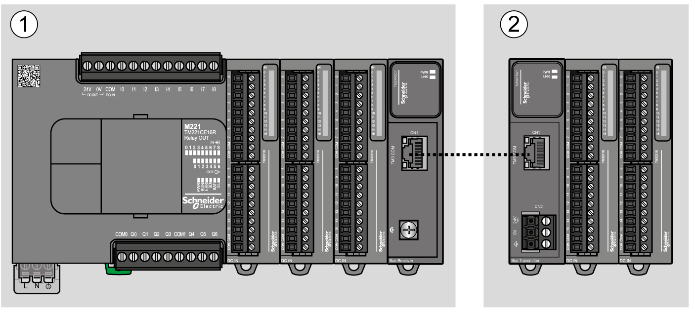
1 Local configuration
2 Remote configuration
The following figure represents the components of a remote configuration:
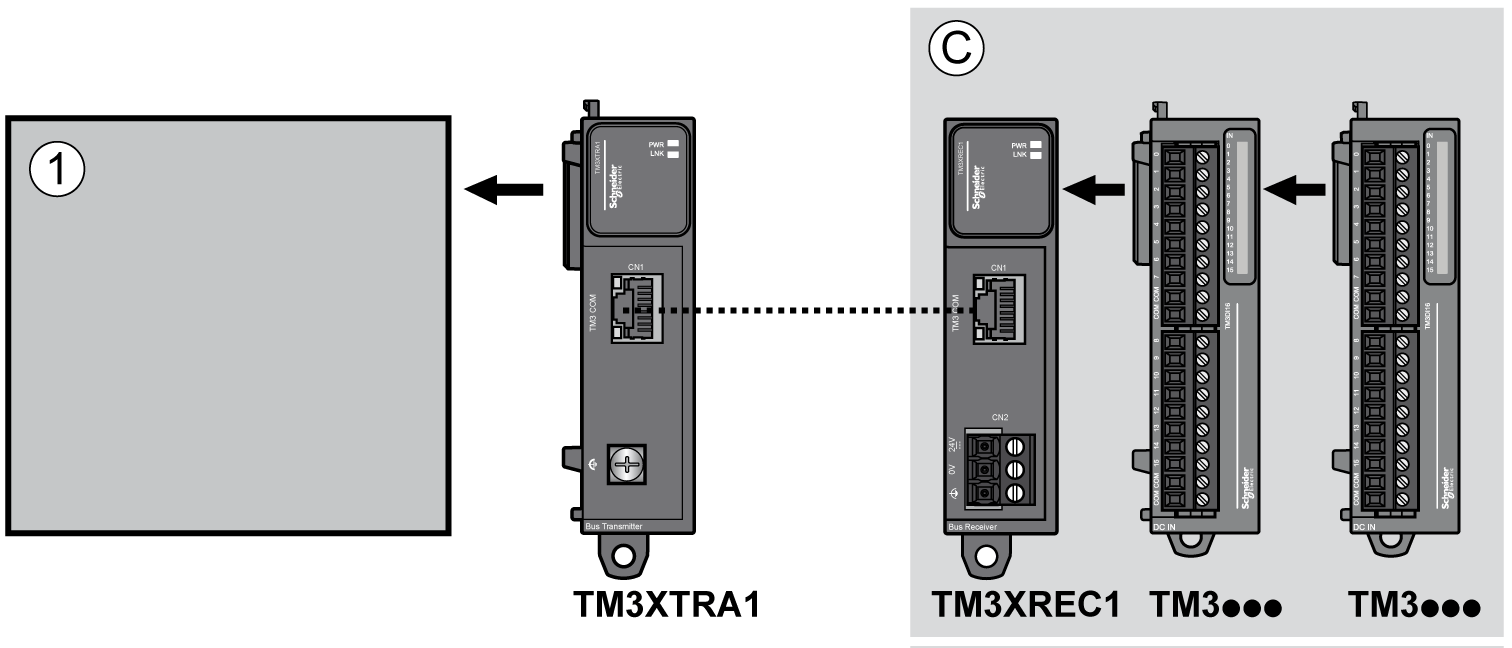
1 Controller and modules
C Expansion modules (7 maximum)
NOTE: Transmitter and receiver modules does not count in the maximum number of expansion modules.
NOTE: You cannot use TM2 modules in configurations that include the TM3 transmitter and receiver modules.
|
Reference |
Description |
Use |
Quantity |
|---|---|---|---|
|
TMAT2PSET |
Set of 5 removable screw terminal blocks |
Connects the 24 Vdc power supply. |
1 |
|
AB1AB8P35 |
End brackets |
Helps secure the logic controller or receiver module and their expansion modules on a top hat section rail (DIN rail). |
1 |
|
TM2XMTGB |
Grounding Bar |
Connects the cable shield and the module to the functional ground. |
1 |
|
TM200RSRCEMC |
Shielding take-up clip |
Mounts and connects the ground to the cable shielding. |
25 pack |
|
TMAM2 |
Mounting Kit |
Mounts the controller and I/O modules directly to a flat, vertical panel. |
1 |
|
Reference |
Description |
Use |
Quantity |
Length |
|---|---|---|---|---|
|
VDIP184546005 |
Actassi CL-MNC5e Patchcord RJ45 cable |
Connects the transmitter to the receiver. |
1 |
0.5 m (1.64 ft) |
|
VDIP184546010 |
1 m (3.28 ft) |
|||
|
VDIP184546020 |
2 m (6.56 ft) |
|||
|
VDIP184546030 |
3 m (9.84 ft) |
|||
|
VDIP184546050 |
5 m (16.40 ft) |
|||
|
Provided with the TM3XTRA1 module |
Functional ground cable |
Connect the functional ground (FE) directly to the conductive backplane. |
1 |
0.12 m (0.39 ft) |