In order to exchange input / output data between the PROFIBUS DP slave module and the PROFIBUS master in a cyclic way, define the variables in the Profibus-Modules I/O Mapping tab.
The %IW addresses of the controller are the output values supplied by the PROFIBUS DP master.
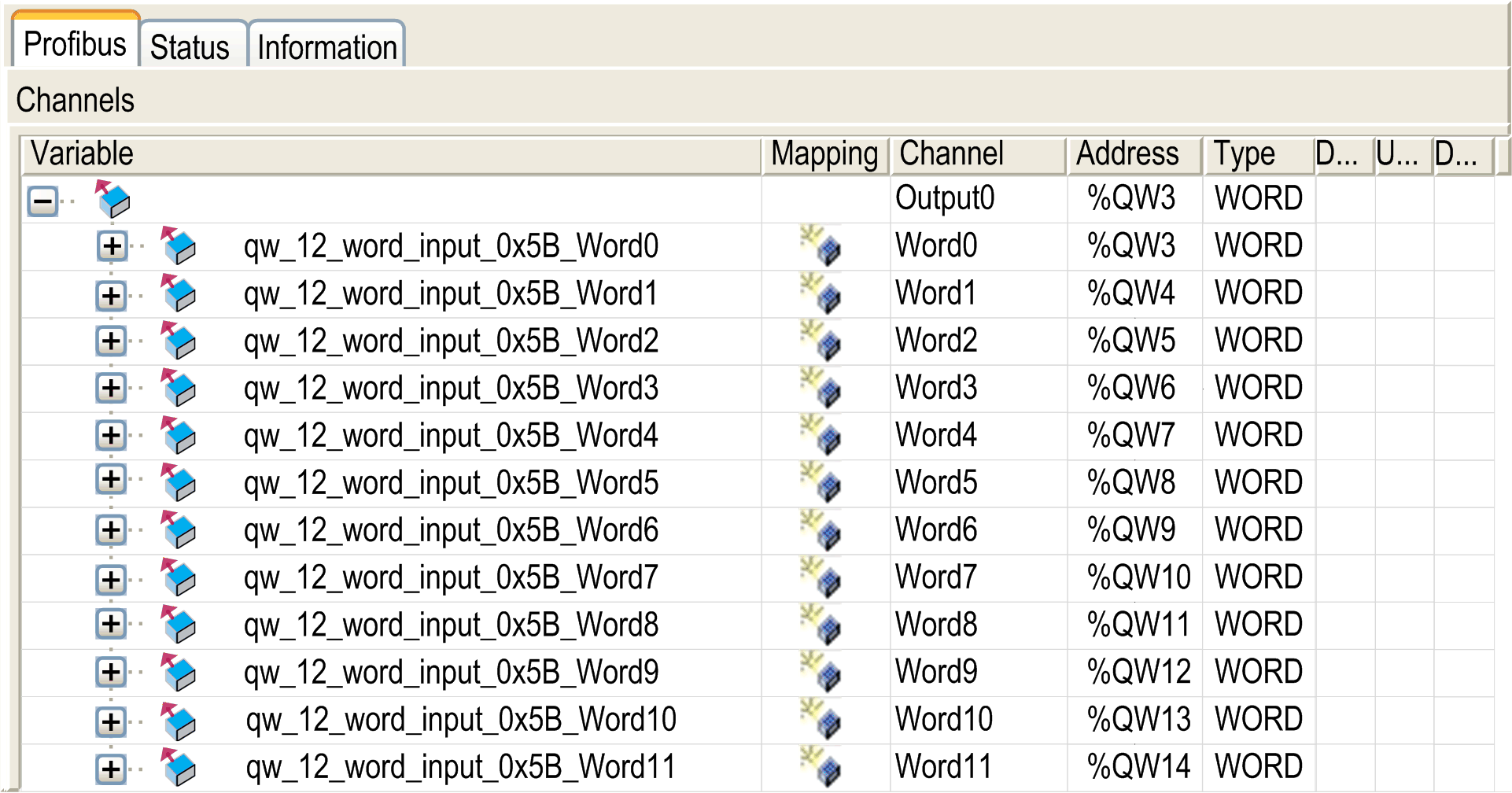
The %QW addresses of the controller are applied to the input of the PROFIBUS DP master.
NOTE:
When you use the PROFIBUS module TM4PDPS1, it is mandatory to:
oconfigure a dedicated PROFIBUS task without watchdog (do not use the MAST task)
oassign the dedicated PROFIBUS task a lower priority than the MAST task (for example, if the MAST task has a priority value 1, the TaskProfibus must have a priority value 10.)
onot set the PROFIBUS task cycle time faster than 10 ms. The typical cycle time of the bus cycle task is 10 ms.
For more information about PROFIBUS task configuration, refer to the EcoStruxure Machine Expert online help, chapter Programming with EcoStruxure Machine Expert / Device Editors / ProfibusDP Configuration Editor / ProfibusDP bus cycle task.
Create Your I/O Mapping Table for the TM4PDPS1 PROFIBUS DP Slave Module
|
Step |
Action |
|---|---|
|
1 |
Select the Devices & Modules tab in the Hardware Catalog and click Communication. |
|
2 |
Select Profibus > Master, choose the I/O device to add and drag-and-drop it onto TM4PDPS1. Result: The module is added to My Controller > COM_Bus > TM4PDPS1 area of the Devices tree. |
The variables for the exchange are automatically created in the %IWx and %QWx of the Profibus I/O Mapping tab. Double-click the I/O device you added to access this screen.
Configure a Virtual I/O Device Added to the TM4PDPS1 Module
The tabs of the configuration window are described in the table below:
The configuration window contains the following tabs:
|
Tab Name |
Description |
|---|---|
|
Profibus I/O Mapping |
This tab contains the variables for data exchange. |
|
Status |
This tab provides diagnostic information. |
|
Information |
This tab provides further information on the selected input or output module. |
The table describes the status of the PROFIBUS I/O depending on:
othe controller status
othe PROFIBUS communication state (value of PROFIBUS_R.i_CommState of PLCSystem library)
|
Controller State |
Controller PROFIBUS I/O State |
|---|---|
|
STOPPED |
The %QW addresses are managed as it is configured in the PLC Settings tab of the controller configuration screen. The %IW addresses are managed as it is configured in the PLC Settings tab of the controller configuration screen. |
|
RUNNING |
The %IW addresses are updated by the master. The %QW addresses are sent to the master. |
|
HALT |
The %QW addresses are managed as it is configured in the PLC Settings tab of the controller configuration screen. The %IW addresses keep the last correct value sent by the master. |
|
Communication Status |
Value of PROFIBUS_R.i_CommState |
Controller PROFIBUS I/O State |
|---|---|---|
|
PROFIBUS Master is stopped |
4 (Operate mode) |
The %IW addresses are set to 0 by the master. The %QW addresses are sent to the master. |
|
Watchdog is detected |
2 (Stop) |
The %QW addresses are not sent to the master. The %IW addresses keep the last correct value sent by the master. |