The table below describes the main characteristics of the TM5SDM12DT electronic module:
|
Main Characteristics |
|
|---|---|
|
Number of input channels |
8 |
|
Input type |
Type 1 |
|
Input signal type |
Sink |
|
Number of output channels |
4 |
|
Output type |
Transistor |
|
Output signal type |
Source |
|
Output current |
0.5 A max. |
|
Rated input voltage |
24 Vdc |
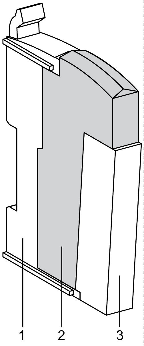
The illustration below shows the TM5SDM12DT:

The table below shows the model numbers for the terminal block and the bus bases associated with the TM5SDM12DT:
|
Number |
Model Number |
Description |
Color |
|---|---|---|---|
|
1 |
TM5ACBM11 or TM5ACBM15 |
Bus base
Bus base with address setting |
White
White |
|
2 |
TM5SDM12DT |
Electronic Module |
White |
|
3 |
TM5ACTB12 |
Terminal block, 12 pins |
White |
NOTE: For more information, refer to TM5 bus bases and terminal blocks.
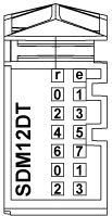
The following illustration describes the LEDs for TM5SDM12DT:

The table below shows the TM5SDM12DT input status LEDs:
|
LED |
Color |
Status |
Description |
|---|---|---|---|
|
r |
Green |
Off |
No power supply |
|
Single flash |
Reset state |
||
|
Flashing |
Preoperational state |
||
|
On |
Normal operation |
||
|
e |
Red |
Off |
OK or no power supply |
|
Single flash |
Error detected on output channels 1 |
||
|
e+r |
Steady red / Single green flash |
Invalid firmware |
|
|
0 - 7 |
Green |
Off |
Corresponding input deactivated |
|
On |
Corresponding input activated |
||
|
0 - 3 |
Yellow |
Off |
Corresponding output deactivated |
|
On |
Corresponding output activated |
||
|
NOTE: The e LED flashes when detecting one of the following errors on output channels: oShort-circuit oOverload oNo 24 Vdc Power Segment supply and an output is at logic 1 |
|||