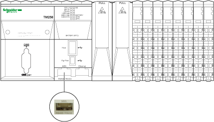
The following illustration shows the location of the Serial Line port of the controller:
The serial line:
ois used to communicate with devices supporting the Modbus protocol as either master or slave, ASCII protocol (printer, modem...) and EcoStruxure Machine Expert Protocol (HMI,...).
oprovides a 5 Vdc power distribution.
For further details, please refer to Serial Line - Planning and Installation.
|
Characteristic |
Description |
|---|---|
|
Standard |
RS485 1 or RS232 software configured |
|
Connector type |
RJ45 |
|
Baud rate |
300 up to 115200 bps 2 |
|
Protocol supported |
oASCII oModbus (RTU or ASCII) oEcoStruxure Machine Expert |
|
Device power distribution |
5 Vdc / 200 mA |
|
5 Vdc Protection |
Withstands up to 24 Vdc |
|
Isolation |
See note 3 |
|
Polarization |
Two 560 Ω resistors switched on or off by software configuration |
NOTE:
1 To isolate the Serial Line RS485, use the TWDXCAISO T-junction box Insulation Modbus RS485.
2 The maximum Baud rate for the Serial Line Port depends on the protocol used. For further information, refer to Serial Line Configuration.
3 The isolation of the electronic module is 500 Vac RMS between the electronics powered by TM5 power bus and the part powered by 24 Vdc I/O power segment connected to the module. In practice, the TM5 electronic module is installed in the bus base, and there is a bridge between TM5 power bus and 24 Vdc I/O power segment. The two power circuits reference the same functional ground (FE) through specific components designed to reduce effects of electromagnetic interference. These components are rated at 30 Vdc or 60 Vdc. This effectively reduces isolation of the entire system from the 500 Vac RMS.
The following illustration shows the pins for RS485 and RS232:
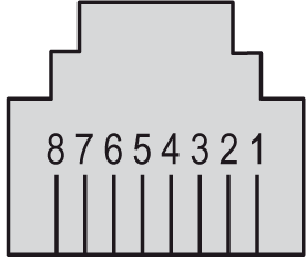
The following table describes the pins for RS485 and RS232:
|
Pin |
RS485 |
RS232 |
|---|---|---|
|
1 |
N.C. |
|
|
2 |
N.C. |
|
|
3 |
N.C. |
|
|
4 |
D1 (A+) |
N.C. |
|
5 |
D0 (B-) |
N.C. |
|
6 |
N.C. |
|
|
7 |
5 Vdc / 200 mA |
5 Vdc / 200 mA |
|
8 |
0 Vdc |
0 Vdc |
CTS: Clear To Send
N.C.: No Connection
RTS: Ready To Send
RxD: Received Data
TxD: Transmitted Data
|
|
|
UNINTENDED EQUIPMENT OPERATION |
|
Do not connect wires to unused terminals and/or terminals indicated as “No Connection (N.C.)”. |
|
Failure to follow these instructions can result in death, serious injury, or equipment damage. |
The following illustration shows the LEDs on the front panel display:
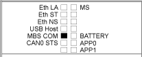
The following table describes the Serial line status LED:
|
Marking |
Description |
LED |
|
|---|---|---|---|
|
Color |
Description |
||
|
MBS COM |
Serial line port activity |
Yellow |
Rapid flashing when frames are received or transmitted |
